
Square-wave generator with 555

The circuit utilizes a 555 timer IC configured in astable mode to generate a continuous square wave output with a 50% duty cycle across various frequency settings. The 555 timer is a versatile integrated circuit that can be used for timing applications, pulse generation, and oscillator functions.
In this configuration, the timing resistor plays a crucial role in determining the frequency of oscillation. The output frequency (f) can be calculated using the formula:
\[ f = \frac{1.44}{(R1 + 2R2) \times C} \]
where R1 is the timing resistor, R2 is a second resistor that can be adjusted for frequency variation, and C is the timing capacitor connected to the discharge pin of the 555 timer. For a 50% duty cycle output, R1 and R2 should be chosen such that their values are equal, or R2 should be set to zero, effectively creating a symmetric waveform.
The circuit typically includes a capacitor connected between the threshold and discharge pins and ground, which charges and discharges through the timing resistors, thus generating the square wave. The output pin of the 555 timer provides a square wave signal that can be used to drive other circuits or as a clock signal for digital applications.
To ensure stability and reliability, decoupling capacitors may be added close to the power supply pins of the 555 timer. This configuration allows for easy adjustments of frequency by varying the values of the resistors or the capacitor, making it suitable for a range of applications from simple timers to more complex pulse modulation systems.A single timing resistor ensures that the output is a square (50% duty cycle) wave at all frequency settings. any 555 type of chip will do the job.
Related Circuits
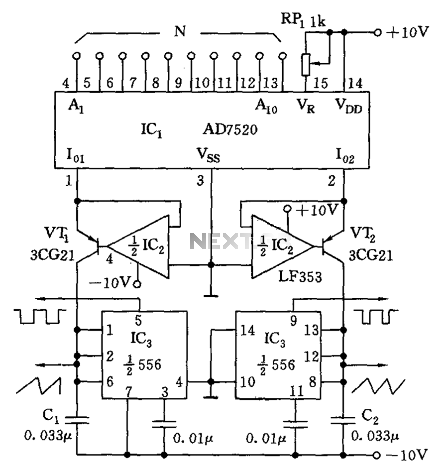
As shown in the figure, the AD7520 is a CMOS type integrated circuit Digital-to-Analog Converter (DAC) featuring 10 channels. It can provide 10 N-bit digital outputs that are proportional to the input current Io1, as well as outputs that...
The circuit was originally available in kit form from a surplus supplier, but it is likely more widely accessible now. It introduces innovative concepts such as utilizing a 555 timer as a pulse width modulator (PWM) and employing serial/parallel...
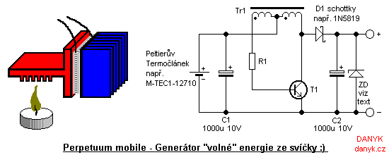
Introduction: This device is not a true perpetual motion machine or a source of free energy from the atmosphere; however, it presents an intriguing experiment, particularly for beginners and enthusiasts of alternative energy sources. It enables the generation of...

This circuit represents a waveform generator, which is highly beneficial for electronic experiments and design. It primarily generates sine wave oscillations, but the circuit can be modified to produce triangle or square wave functions. The circuit is based on...

The voltage rating of the 470 µF capacitor is not critical, provided it significantly exceeds the maximum power supply voltage, which is 12 volts in this circuit. It is essential to connect this capacitor correctly, observing its polarity. The...

This circuit generates clean logic pulses with minimal current consumption. It is designed to produce short 2 ms pulses at a frequency of one pulse per second, drawing only 1 microamp from a 9-volt battery. The described circuit operates efficiently by...