
Xenon Strobe Light Circuit with IC555
The circuit integrates a 555 timer configured in astable mode to create a PWM signal, which is essential for controlling the brightness of a flash in a camera application. The duty cycle of the PWM signal, which is adjustable, directly influences the amount of power delivered to the flash unit. This is achieved by varying the resistance and capacitance in the timing circuit of the 555 timer, which in turn modifies the pulse width.
The P-channel MOSFET (IRF9Z20) serves as a switch that is controlled by the output from the 555 timer. When the output on pin 3 of the 555 timer is low, the MOSFET turns on, allowing current to flow through the flash circuit. The inclusion of a 100-ohm resistor between the 555 timer and the MOSFET gate is crucial as it helps to mitigate any potential parasitic oscillations that could lead to erratic behavior of the MOSFET, ensuring stable operation.
The circuit can be further enhanced by incorporating additional components such as a microcontroller for more complex control over the PWM signal, allowing for features like adjustable flash duration and intensity based on ambient light conditions. Additionally, integrating a feedback mechanism can improve the accuracy of the flash output, ensuring consistent performance across different operating conditions. This design exemplifies the versatility and practicality of using a 555 timer in modern electronic applications, particularly in DIY projects where cost-effective solutions are sought.The circuit used to come in kit form with a surplus supplier, but it is probably more available. It shows some new concepts such as using a 555 as a pulse width modulator (PWM), and serial / parallel processors flash camera. The 555 is mounted as a pulse width modulator (from the (low) time to be determined by the regulator).
The output on pin 3 i s connected to the gate of P-channel MOSFET (IRF9Z20) through the 100R resistor to prevent parasitic oscillation of the transistor. A low signal on pin 3 causes the MOSFET to turn, so the button controls the flash output and a bit rate, by varying the duty cycle of 555 and in turn the MOSFET.
Be the first of your friends to get free diy electronics projects, circuits diagrams, hacks, mods, gadgets & gizmo automatically each time we publish. Your email address & privacy are safe with us ! 🔗 External reference
Related Circuits
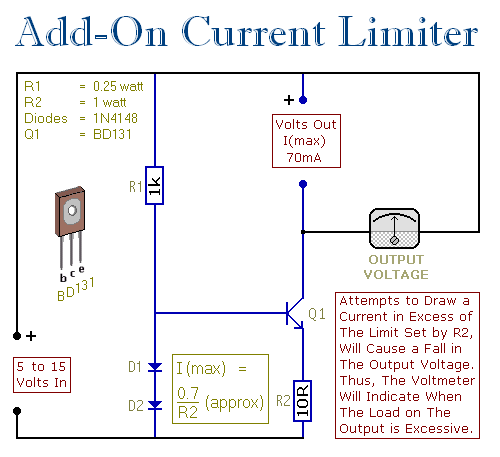
This circuit allows setting a limit on the maximum output current from a power supply unit (PSU). It is particularly useful when powering up a project for the first time or conducting a soak test. By establishing an upper...

Battery vampires are circuits designed to extract as much energy as possible from batteries or cells. They are not regulated drivers; rather, they are boost circuits that create a higher output voltage from a low input voltage and provide...

Even including labor, the actual cost of purchasing, stocking, assembly, assembly errors, more expensive PCBs (with additional holes and larger sizes), and the increased difficulty in tuning would likely result in significantly higher expenses. The analysis of costs associated with...

This house FM transmitter for your stereo or any other amplifier provides a good signal strength up to a distance of 500 meters with a power output of about 200 mW. It operates on a 9V battery. The audio-frequency...
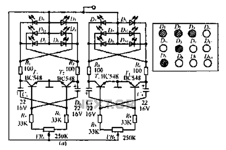
A circuit involving oscillations is composed of a Houle Wang oscillator that utilizes a transistor configuration with components labeled Ti, n, and n, along with a composition of Q constants for the cycle. The waveform can be modified by...

The add-on circuit presented here is useful for stereo systems. This circuit has provisions for connecting stereo outputs from four different sources or channels as inputs, with only one of them selected and connected to the output at any...