
Square Wave Oscillator
This circuit operates primarily using a 555 timer IC configured in astable mode to generate square wave signals at selectable frequencies. The circuit can be adjusted to produce six distinct frequencies, typically ranging from 1 Hz to higher values, allowing for versatile testing of both analog and digital circuits. The 555 timer's output is connected to a series of output components, including resistors and capacitors, which help manage the signal strength and ensure compatibility with various circuit inputs.
To implement the circuit, the frequency selection is achieved through jumper leads that connect to specific points in the circuit, allowing for easy adjustments. The inclusion of a potentiometer provides the flexibility for variable frequency generation, although it is important to carefully select the potentiometer value to maintain the desired frequency range.
The LED indicator serves as a visual confirmation of the circuit's operation, providing immediate feedback during testing. For effective use, the signal injector should be connected to the input stage of the radio or TV being tested, generally starting from the volume control end. As the signal is injected, it is crucial to monitor the output, adjusting the resistors and capacitors as necessary to prevent signal overload and ensure accurate testing results.
In summary, this signal injector circuit is a practical and essential tool for electronics troubleshooting, offering a reliable means of generating test signals across a broad frequency spectrum for various applications in radio and television servicing, as well as digital circuit testing.It`s most useful application is as a Signal Injector for radios and TV`s. A square wave is the most suitable for testing the IF (Intermediate Frequency) strip as the signal will pass through the IF transformers without any attenuation, no matter what the tuned frequency of the circuit. Normally only a sine wave of the correct frequency will get through but a square wave can be considered to be a composition of all of the
multiples of a sine wave and no matter what the frequency of the tuned circuit, it will be processed. This project can also be used to test digital circuits by providing a clock pulse, using one of the 6 frequencies to determine if a circuit can be "clocked.
" In fact it`s an invaluable piece of servicing equipment and I have used a similar device for testing the IF strip of TV`s on the odd occasion when a fault developed, and it located the trouble very quickly. The 6 frequencies are selected with a jumper lead and increment in decade values as is standard with test equipment.
If you want the frequency to be variable, you can use a pot between pins 6 and 7 of the 555, instead of the capacitors, but keep in mind that you cannot get the same range by using a single pot - that`s why we have used capacitors. Make a short wander lead with hook-up wire and tin the end so that it fits into the hollow pins. Put the lead into the 1Hz position and connect the battery. You will see the LED flash on and off to prove the circuit is working. Change the lead to one of the higher frequencies and inject the signal into the IF strip of a radio. Start at the volume control end and work your way to the antenna. As you move through the strip, the signal strength will increase and you should compensate for this by adding resistors and capacitors on the output to reduce the signal.
You can also check any of our FM transmitters by picking up the tone on any radio tuned into the transmission. 🔗 External reference
Related Circuits
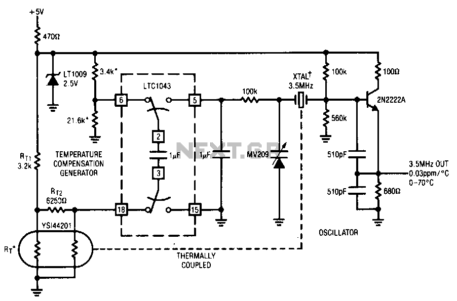
This circuit employs the LTC1043 to distinguish between a temperature sensing network and a de reference. The single-ended output biases a varactor-tuned crystal oscillator to compensate for drift. The varactor crystal network exhibits high de impedance, negating the necessity...
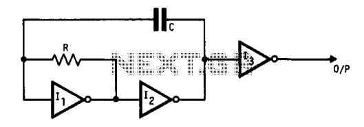
This oscillator utilizes standard inverters, one resistor, and one capacitor, and it does not have a minimum operating frequency. The resistor (R) and capacitor (C) must be selected to ensure that the currents flowing into the gates remain below...
One of the simplest methods of metal detecting is through a beat frequency oscillator. The circuit consists of two balanced oscillators: one provides a reference signal, while the other acts as the detector element. The frequency of the reference...
The circuit illustrates a straightforward triangle and square wave generator utilizing a common dual operational amplifier, the LM1558, capable of producing very low frequencies around 10 kHz. The time interval for one half-cycle is approximately determined by the product...

A series of LEDs that turn on and off in a precise sequence, creating a calming and hypnotic effect. Various LED chaser, scanner, and sequencer circuits exist, utilizing discrete transistors, logic integrated circuits (ICs), or microcontrollers. However, a common...
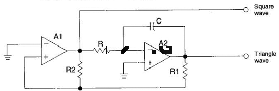
The circuit generates precision triangle and square waves. The output amplitude of the square wave is determined by the output swing of operational amplifier A1, while the ratio of resistors R1 to R2 sets the amplitude of the triangle...