
Audio Triangle Square Wave Generator Using Op-Amp
The triangle and square wave generator circuit is designed using the LM1558 dual operational amplifier, which is a versatile component for generating low-frequency waveforms. The circuit operates by charging and discharging a capacitor through resistors, creating a linear ramp voltage that forms the triangle wave. The square wave is derived from the triangle wave by using a comparator configuration within the operational amplifier.
In this configuration, the timing components consist of a resistor (R) and a capacitor (C) connected in an RC network that determines the frequency of oscillation. The relationship between R, C, and frequency can be expressed as f = 1/(2πRC), where f is the frequency of the output waveform. For a target frequency of around 10 kHz, suitable values for R and C must be selected to meet this requirement.
The amplitude of the triangle wave output is adjustable via the 47 kΩ resistor. By changing this resistor's value, the charging and discharging rates of the capacitor are altered, thus varying the peak-to-peak voltage of the triangle wave. Additionally, to eliminate any DC offset in the output waveform, a capacitor can be placed in series with the output. This capacitor blocks any DC component, allowing only the AC signal to pass through, ensuring a cleaner output signal.
Overall, this circuit provides a reliable method for generating triangle and square waves at low frequencies, making it suitable for applications in signal processing, waveform generation, and testing electronic components. Proper component selection and configuration are crucial for achieving the desired output characteristics.The circuit shows a simple triangle and square wave generator with a common dual operational amplifier LM1558 to produce very low frequencies around 10 kHz. The time interval for one half cycle is about R * C and outs of supply of 10 mA. The amplitude of the triangle can be altered by adjusting the 47K and waveform offset can be eliminated by addi
ng a capacitor in series with the output. 🔗 External reference
Related Circuits
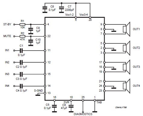
This circuit illustrates a car audio amplifier utilizing the TDA7381 integrated circuit (IC). The TDA7381 audio amplifier IC allows for the design of a straightforward 4x25 watts car radio. The TDA7381 is a high-performance audio amplifier designed specifically for automotive...
To achieve optimal performance from an NBTV signal, it is crucial to utilize the complete dynamic range of the signal without any crushing at the black level or peak white. To evaluate the linearity of a video path, it...
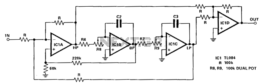
The circuit illustrated here demonstrates that the response at one octave off-tune remains within 10% of the far-out response. The sharpness of the notch can be adjusted by increasing or decreasing the 68-ohm resistor. The linearity tracking of resistors...
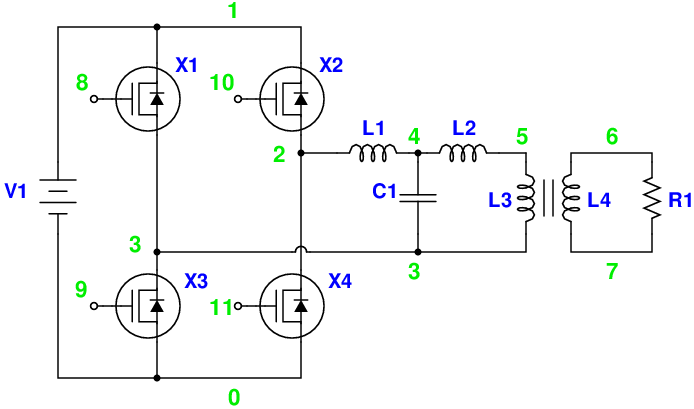
Magic Sinewave Analysis using SPICE and a Simple Inverter Circuit. This document discusses the analysis of a sinewave signal generated by a simple inverter circuit using SPICE simulation software. The inverter circuit is designed to convert a DC input voltage...
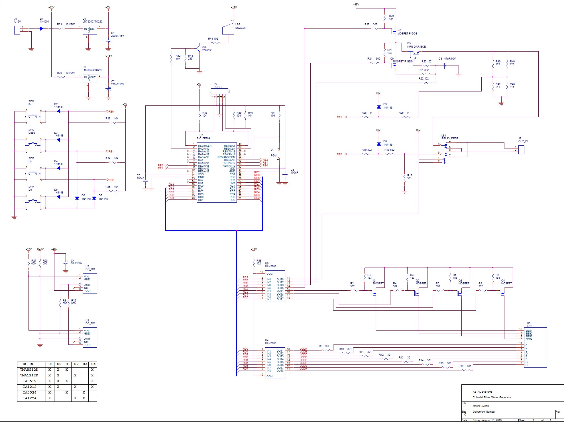
By selecting the "ON" mode, the SilverPro© initiates the process of generating colloidal solutions using the preset parameters configured by the user. The unit always recalls the last used presets. During operation, the display alternates between the total elapsed...
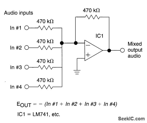
The circuit features four inputs. The voltage gain between each input and the output is maintained at unity by the relative values of the 470kΩ input resistor and the 470kΩ feedback resistor. The described circuit operates as a voltage buffer...