
Stabilized DC Power Supply with Short-Circuit Indication
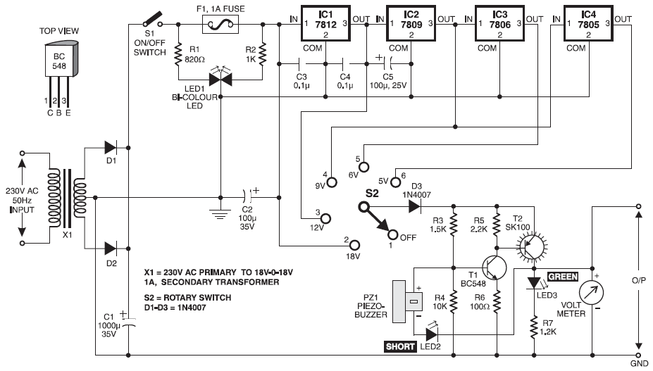
The stabilized DC power supply circuit is designed to cater to various electronic testing requirements by providing multiple voltage outputs. The use of a rotary switch S2 allows for easy selection between the different regulated outputs, ensuring flexibility for different applications. The analog voltmeter serves as a crucial component for monitoring the output voltage, allowing users to verify that the desired voltage level is being supplied.
The circuit employs a center-tap transformer to achieve the necessary voltage levels, which is essential for generating both positive and negative outputs. The full-wave rectification process, facilitated by diodes D2 and D3, ensures that the output voltage is smooth and stable, minimizing ripple and fluctuations. Capacitors C1 and C2 play pivotal roles in filtering and stabilizing the output, contributing to the overall performance of the power supply.
The incorporation of short-circuit indication features enhances safety during operation, alerting users to potential issues with the connected load. This is particularly important in testing scenarios where sensitive components may be at risk. The dual regulated output design allows for simultaneous powering of multiple circuits, which is advantageous in complex testing environments.
The DC to DC converter based on the LM2596 provides an additional layer of versatility, capable of stepping down higher input voltages to the required output levels while maintaining efficiency. The specified output ratings ensure that the circuit can handle a range of applications, from low-power devices to more demanding loads.
Overall, this stabilized DC power supply circuit is a comprehensive solution for electronic testing, offering reliability, safety features, and adaptability to various voltage requirements. The additional water-level indicator circuit exemplifies the versatility of the design, showcasing its potential applications beyond just power supply functionalities.Stabilized DC Power Supply with Short-Circuit Indication. The circuit gives you four different regulated DC outputs (12V, 9V, 6V and 5V) and an unregulated 18V DC output, that are selectable by way of rotary switch S2. The selected output is showed on the analogue voltmeter connected to the outputs rails. This is definitely an effective 4-output s tage stabilized DC power supply unit for testing electronic circuits. It delivers very well regulated and stabilised output, that is important for most electronic circuits to provide good results. The circuit gives you an audio-visual indication if there is a short circuit in the PCB under test, so the.
This is a dual regulated and stabilized power supply, usually used to supply amplifier circuit. There are 3 output that are (+) voltage, (0) Ground (normal), and (-) voltage. The current output max about 0. 3-0. 5 A. Please take a note that this circuit require center tap transformer. for example, if you need 12v output, you. This circuit generates 3 source regulated voltages applying a minimum of electronic parts. The output DC voltage are +12V ; +5V and -5V. Diodes D2 and D3 conduct full-wave rectification, at the same time charging capacitor C2 on each halves of the alternating current cycle. At the same time, diode D1 with capacitor C1, and. This is the circuit diagram of DC to DC converter based LM2596, the circuit has a single input supply and multiple voltage outputs.
The circuit has an input voltage range of 15V to 40V. It has 5 outputs: 3. 3V at 1. 5A; +12V and ’12V at 50 mA each; and +5V and ’5V at 50 mA. The above diagram is a basic Uninterupted Power Supply (UPS) circuit. This is a very simple and inexpensive circuit. This circuit can be adapted/modified for other regulated and unregulated voltages by using different regulators and batteries. For a 15 Volt regulated supply, you may apply two 12V batteries connected in series (it will become 24V).
Here the water-level indicator which use a 7-segment display, to show the water level (low, half and full) in the tank. Moreover, a buzzer is utilized to warn you of water overflowing from the tank. The circuit shows the water level by displaying L, H and F for low, half and full, respectively. The circuit. 🔗 External reference
Related Circuits
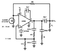
This device has a quiescent power drain of 24 milliwatts when operating from a 6 V supply, making the LM386 ideal for battery operation. According to the application hints section of the LM386 datasheet, two pins (1 and 8)...
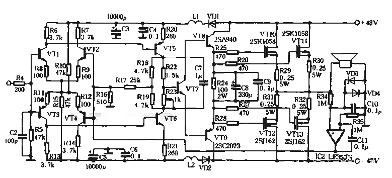
The self-designed amplifier circuit described is completely symmetrical and complementary, effectively utilizing the advantages of complementary NPN and PNP transistors to achieve a high degree of stability. The circuit features good symmetry in the push-pull amplification state, allowing for...
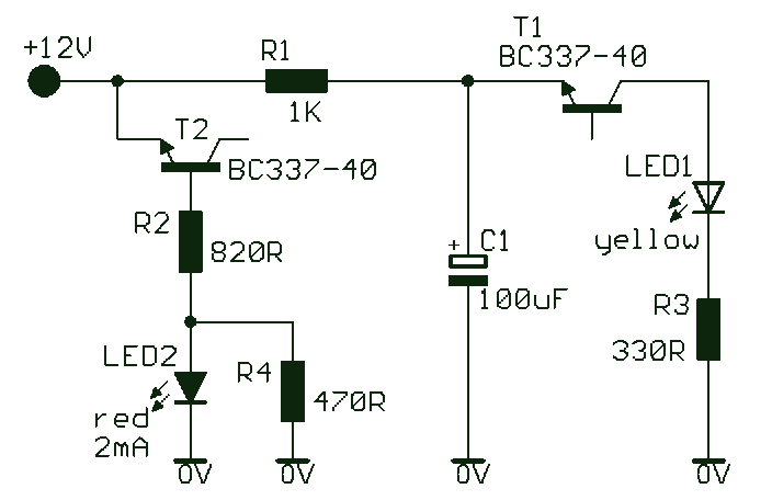
A novel supply voltage monitor which uses a LED to show the status of a power supply. This simple and slightly odd circuit can clearly show the level of the supply voltage (in a larger device): as long as...
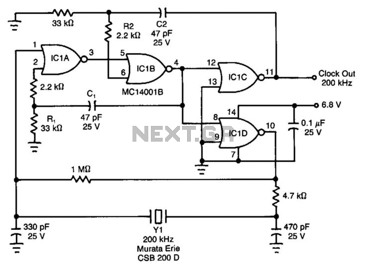
Ceramic resonators are suitable for low-power, low-frequency clock sources, despite their 30-ppm temperature coefficient. However, they exhibit troublesome spurious-resonance modes. This circuit effectively rejects all but the fundamental mode of the resonator. The clock circuit operates within a temperature...
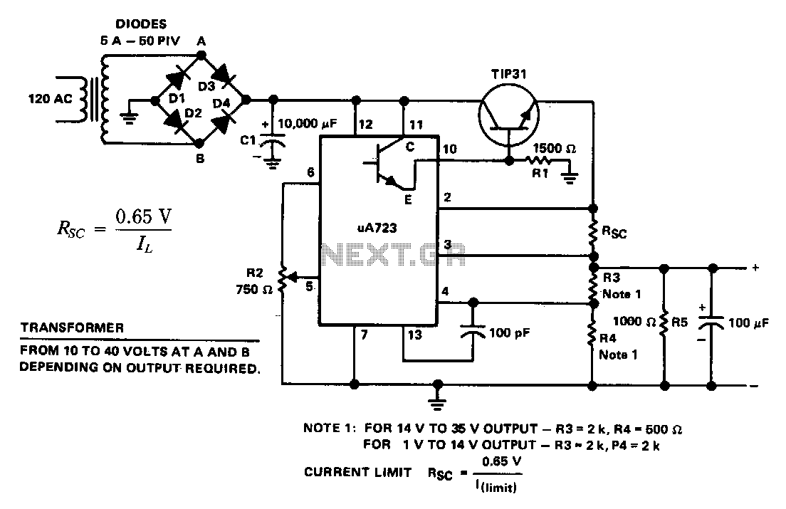
The supply 6-66 can be utilized for output voltages ranging from 1 to 35 V. The line transformer must be selected to provide approximately 1.4 times the desired output voltage from the positive side of filter capacitor C1 to...
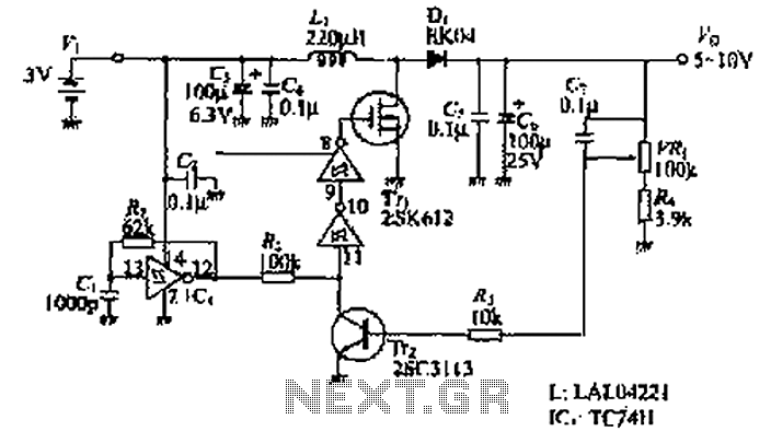
The design of the power supply circuit diagram utilizes an oscillator circuit from the 74HC series of CMOS logic circuits, with a MOSFET as the switching device. This configuration allows for the development of small-scale power supplies suitable for...
Warning: include(partials/cookie-banner.php): Failed to open stream: Permission denied in /var/www/html/nextgr/view-circuit.php on line 713
Warning: include(): Failed opening 'partials/cookie-banner.php' for inclusion (include_path='.:/usr/share/php') in /var/www/html/nextgr/view-circuit.php on line 713