
Step-up switching power supply circuit diagram
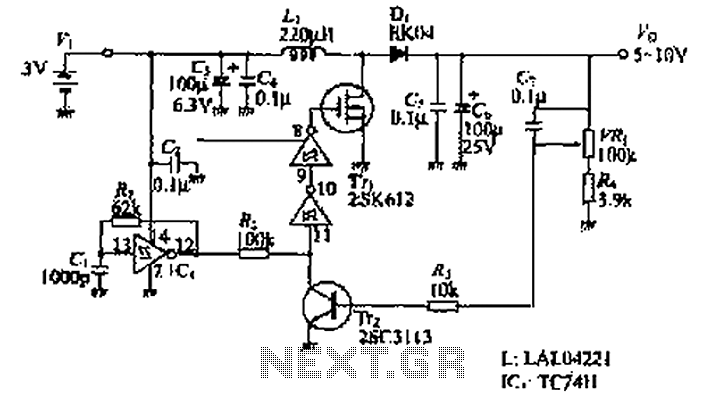
The power supply circuit leverages the 74HC series, known for its high-speed performance and low power consumption, making it ideal for battery-operated devices. The oscillator circuit generates a square wave signal that drives the gate of the MOSFET, enabling efficient switching. The MOSFET, chosen for its high efficiency and fast switching capabilities, acts as a switch that controls the flow of current to the load.
In this design, the oscillator frequency can be adjusted to optimize the performance of the power supply, ensuring that it meets the specific voltage and current requirements of the portable appliances it powers. The circuit may include additional components such as capacitors for filtering and resistors for biasing, which help stabilize the output voltage and minimize ripple.
The compact nature of this power supply design allows it to be integrated into various portable devices, providing reliable power while maintaining a lightweight and space-efficient profile. This versatility makes it suitable for a wide range of applications, from consumer electronics to medical devices, where portability and efficiency are paramount. As shown in the design of the power supply circuit diagram. Using the oscillator circuit 74HC series CMOS logic circuit, the switching device is MOSFET. This means the number o f small-scale power supply can be used in portable appliances.
Related Circuits
The MAX34446 data logger for power supplies is capable of monitoring voltages for overvoltage and undervoltage conditions, as well as overcurrent and overtemperature situations. The device continuously checks user-programmable thresholds. The MAX34446 is an advanced monitoring solution designed for power...
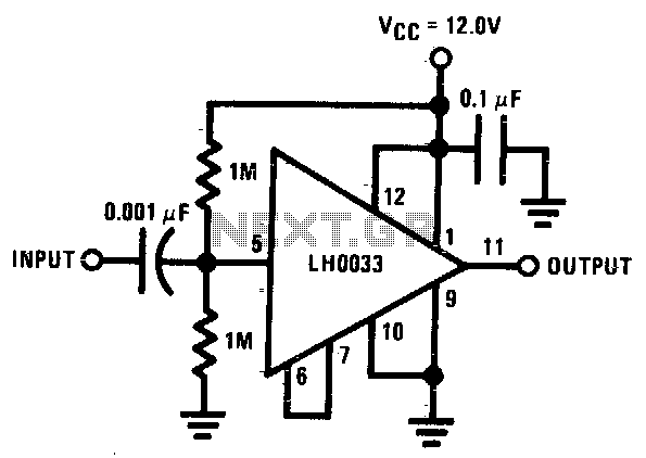
The input is DC biased to the mid-operating point and is AC coupled. Its input impedance is approximately 500K ohms at low frequencies. For DC loads referenced to ground, the quiescent current is increased by the load current set...
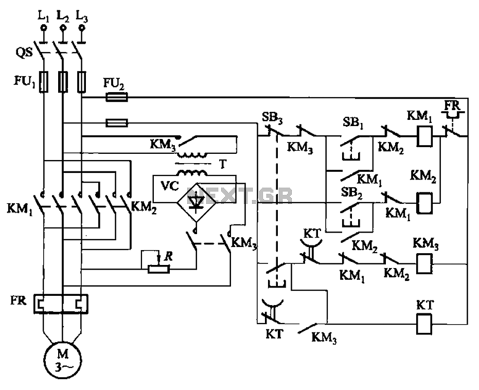
The circuit illustrated in Figure 3-144 depicts an automatic control system for dynamic braking. It utilizes a time relay (KT) to manage the operational duration, along with a step-down transformer (T) and a single-phase bridge rectifier. The circuit includes...
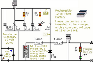
The following circuit illustrates an Alarm Power Supply Circuit Diagram. Features include a 1-amp current output, suitable for a Modular Burglar Alarm operating at 12 volts. The Alarm Power Supply Circuit is designed to provide a stable and reliable power...
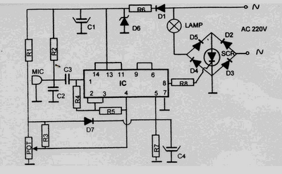
This 220 Volt disco lamp circuit is not a voice switch (VOX), as it cannot differentiate between musical sounds and human voices. Instead, it functions as a sound-activated device. An interesting application of this circuit is to control the...
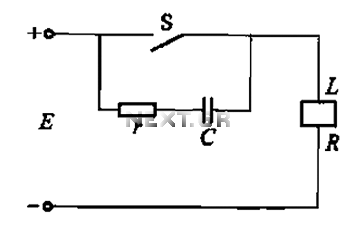
A resistor-capacitor circuit designed to prevent spark blowout. The coil's magnetic energy is converted into electrical energy stored in the capacitance C, effectively suppressing sparks and enhancing safety. The circuit is capable of functioning normally even with reverse polarity....
Warning: include(partials/cookie-banner.php): Failed to open stream: Permission denied in /var/www/html/nextgr/view-circuit.php on line 713
Warning: include(): Failed opening 'partials/cookie-banner.php' for inclusion (include_path='.:/usr/share/php') in /var/www/html/nextgr/view-circuit.php on line 713