
100W switching power amplifier circuit
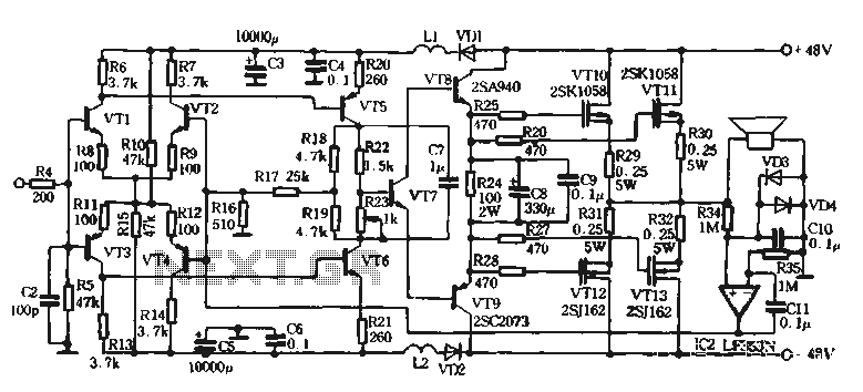
The amplifier circuit is designed to maximize audio performance while minimizing distortion and phase shift. The symmetrical and complementary design of the NPN and PNP transistors ensures that both halves of the audio signal are amplified equally, which is crucial for maintaining audio fidelity. By eliminating coupling capacitors, the circuit avoids potential phase shifts that can degrade sound quality, particularly in high-frequency ranges.
The differential amplifier stage, using a long tail configuration, allows for better signal processing and noise reduction compared to traditional designs. The quiescent current settings are critical; they establish a baseline operational state that optimizes signal-to-noise ratios while preventing thermal runaway in the transistors. The feedback network is carefully designed to provide stability across varying loads and input signals, ensuring that the amplifier can handle dynamic audio without distortion.
The output stage's use of high-quality tubes enhances the overall sound character, providing warmth and detail that are often sought after in high-fidelity audio applications. The careful selection of components, including the use of vibration absorption resistors and stabilizing capacitors, contributes to the circuit's robustness and reliability.
In summary, this amplifier circuit exemplifies advanced audio engineering principles, focusing on symmetry, stability, and fidelity, making it suitable for high-performance audio applications. The design considerations and component choices reflect a deep understanding of the interplay between electronic components and audio signal integrity.Self-designed amplifier circuit 9 of the circuit described in this article is completely symmetrical and complementary, can give full play to the advantages of complementary NPN and PNP transistors, so that the whole circuit has a very high degree of stability. Because the signal from input to output at the push-pull amplification state so good symmetry, temple high fidelity circuit signal path without a coupling capacitor homes, no large loop negative feedback.
The circuit becomes a DC amplifier circuit to eradicate the capacitor caused by the presence of dye tone phase shift. Reduced due to large transient counter electromotive force when the depth of the negative feedback loop caused by intermodulation distortion and vibration generated by the speaker voice coil of the front portion of the circuit interference.
So that the conversion rate of the entire circuit is greatly improved. The resolution of a strong small-signal q VT1 ~ VT4 composed of a differential amplifier input stage circuit. The class does not use conventional constant current circuit Henan, while the use of long tail circuits.
Amplifier uses high-frequency switching power supply, stable operating point of the circuit has played a positive role in this 6. Not only simplifies the circuit and make the actual audition t improve sound quality also confirms this.
Each set of differential amplifier quiescent current of ImA, proved in ensuring the premise of an appropriate increase in signal to noise ratio required for this level of input current, this stage quiescent current is 6mA. Negative feedback from the VT6, VT5 collector by R18, R19, R17, R16 leads connected to the input stage of the inverting input interface circuit forming a DC negative feedback magnification by the (R, B R.
ga + R17) / R] 5 decision. Circuit driven by the level VT8.VT9 composition, there is plenty of current output and improve followability instantaneous signal to ensure a large dynamic output, the level static take-state current 32mA, thus improving transient large signal output powerless ills. In addition the size of the current level and tone related. Final output circuit using Hitachi ZSK10582SJ162 sound field effect on the tube, to whichever warm tone, detail the advantages and strong.
Each channel two pairs of parallel, each gate of the string of R25 ~ R28 resistance vibration absorption resistance, the parallel C8. C9 capacitors role is to stabilize the quiescent current bias 6 per tube was adjusted to 480mA, working in class AB mouth due to the current level to promote crystal transistor having a positive temperature coefficient t work when a certain temperature, it is for the installation of a temperature compensation VT7 application taking into account the conditions of the amateur pairing precision transistors, using the midpoint potential servo composed by the lC2 circuit.
Circuit VD1, VD2 is separated to prevent mutual interference from before and after class and added, high-frequency pulse power supply 11 1.2 is only caused by the eye into the front stage and setting. Front -stage filter capacitor C3-cs larger capacity, have a good effect q
Related Circuits
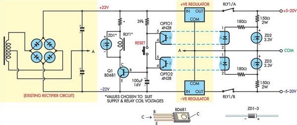
This circuit was designed to protect a dual rail power supply from shorts across the two rails. It uses an optocoupler to monitor each supply rail, with the internal LEDs powered from ZD2 and ZD3 and the associated resistors....

This is a simple power supply that provides a reliable and clear regulated output voltage ranging from 0 to 28 volts with a maximum current of 6 to 8 amperes. Utilizing two 2N3055 transistors allows for doubling the output...
The voltage output is controlled by a 10K variable resistor. The output voltage range is approximately 3 to 15 volts, with a current range of about 10mA minimum and 2A maximum. When the current limit is reached, the output...
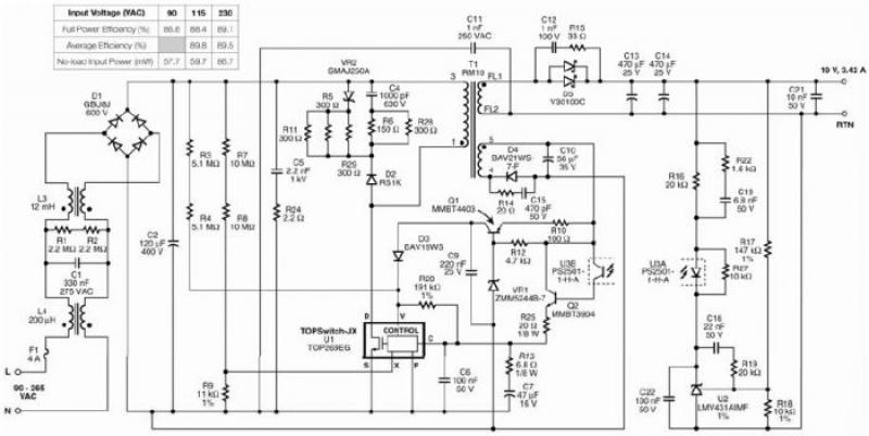
The TOP269EG off-line switcher integrated circuit (IC), designated as U1, can be utilized in a flyback configuration to create a simple and highly efficient power adapter for notebook laptops. The TOP269EG features an integrated 725 V MOSFET and a...
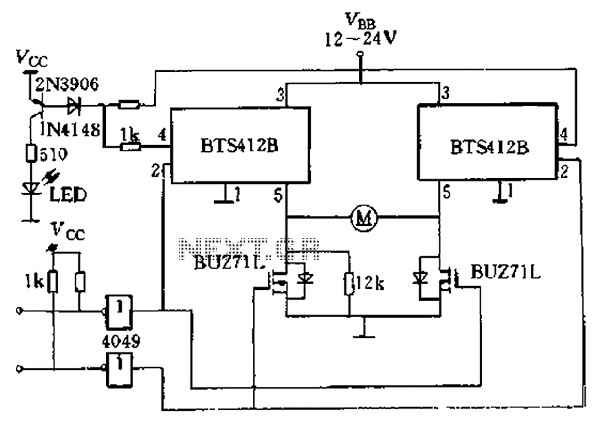
The BTS412B functions as two high-side power MOSFET switches, while two BU271L (50V, Zhang 1n) serve as low-side switches, forming a bi-directional H-bridge DC motor drive circuit. This configuration is designed for electrical automatic door systems, capable of handling...
Magnetic pickups in musical instruments exhibit a relatively high output impedance, which can lead to a decrease in treble response when connected through long cable runs or to equipment with low input impedance. This preamplifier addresses these challenges by...
Warning: include(partials/cookie-banner.php): Failed to open stream: Permission denied in /var/www/html/nextgr/view-circuit.php on line 713
Warning: include(): Failed opening 'partials/cookie-banner.php' for inclusion (include_path='.:/usr/share/php') in /var/www/html/nextgr/view-circuit.php on line 713