
Stable Start-Stop Oscillator

In electronic applications, pulse generators play a crucial role, particularly in video signal processing and timing applications. The described oscillator is designed to produce a specific number of pulses, which can be essential for synchronizing video signals or creating timing references in various circuits.
The operation of this oscillator is initiated by a control signal. Upon receiving a high-level input, the oscillator begins its cycle after a delay of 13 milliseconds. This delay is critical as it allows for the stabilization of the input signal and ensures that the system is ready to operate without introducing timing errors.
Once the control signal transitions to a high state, the oscillator is activated, and it will generate the predetermined number of output pulses. The precise timing and number of these pulses can be adjusted based on the requirements of the application, allowing for flexibility in design.
When the control signal goes low, the oscillator ceases operation immediately. This feature ensures that the circuit can quickly respond to changes in the input signal, making it suitable for dynamic environments where timing is crucial.
In designing such an oscillator, considerations may include the choice of components such as resistors, capacitors, and integrated circuits that can define the frequency and pulse width. Additionally, the circuit may incorporate feedback mechanisms to improve stability and accuracy in pulse generation.
Overall, this type of oscillator is valuable in various electronic systems, providing reliable pulse generation that meets the demands of modern applications, particularly in the realm of video technology. Oscillators that generate a predetermined number of pulses are often required in applications such as video wo rk. This oscillator starts 13 ms after the control signal goes high and stops immediately when the input signal goes low. 🔗 External reference
Related Circuits
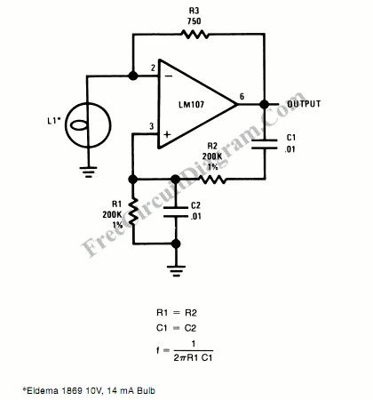
An incandescent lamp has been utilized to reduce harmonic distortion in a sine oscillator circuit. The nonlinear resistance characteristic of the lamp filament assists in this process. In the context of electronic circuits, the use of an incandescent lamp as...
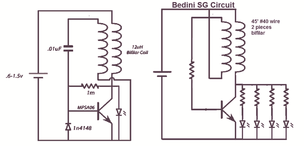
It would be beneficial to obtain schematics of the Joule Thief and Bedini oscillator circuit connections. This is an area that has not been previously explored. The schematic on the left was sourced from the Energetic Forum, while the...
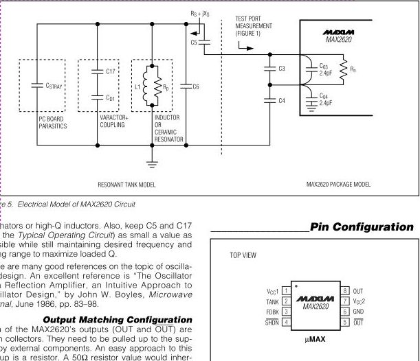
The MAX2620 integrates a low-noise oscillator with two output buffers in a cost-effective, plastic surface-mount, ultra-small uMAX package. This device combines functions that are typically achieved with discrete components. The MAX2620 is designed for applications requiring precise frequency generation with...
The signal can be received using a standard FM radio receiver. It should be coupled by a disc capacitor of approximately 0.1 µF to the main stage. To implement a circuit capable of receiving the specified FM signal, a standard...
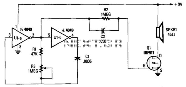
Two gates, U1A and U1B, of a 4049 hex inverter, are connected in a VFO circuit. Components R1, R3, and C1 set the frequency range of the VFO. With the given values, the circuit's output can range from a...
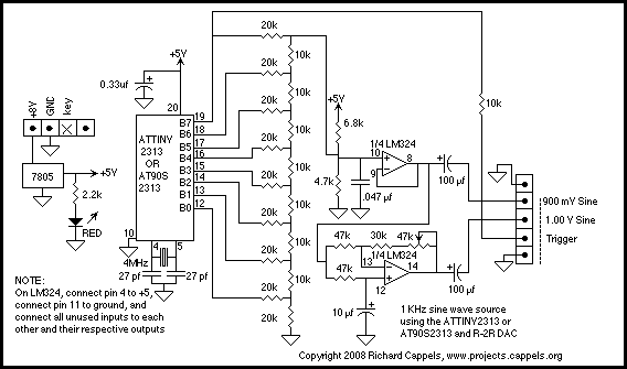
If found myself in need of a 1 KHz signal source for an experiments. My function/sweep generator was needed as a pulse generator for the same experiment, so I went though my junk box, looking for circuits from long...