
Audio Oscillator

The circuit employs two gates from a 4049 hex inverter, specifically U1A and U1B, which are configured as part of a Voltage-Controlled Oscillator (VFO). The primary components that influence the frequency output are resistors R1 and R3, along with capacitor C1. The frequency output of the VFO is adjustable and can span from a few hundred hertz to several thousand hertz, depending on the resistance value set by R3.
The frequency modulation is achieved through the adjustment of R3, which alters the charging and discharging time of capacitor C1, thereby changing the oscillation frequency. Additionally, the circuit design allows for further frequency manipulation by substituting different capacitance values for C1. This can be efficiently implemented using a rotary switch that is connected to a selection of capacitors. By rotating the switch, the user can select from multiple capacitance options, allowing for a versatile frequency range adjustment without needing to physically change components.
In practical applications, this VFO circuit can be utilized in various electronic devices that require frequency generation, such as signal generators, tone generators, or in communication systems. The choice of the 4049 hex inverter provides a reliable and straightforward method for creating oscillatory signals, making it suitable for both amateur and professional electronic projects. The overall design emphasizes flexibility and ease of use, allowing for quick adjustments to meet specific frequency requirements. Two gates, U1A and U1B O/3 of a 4049 hex inveter), are connected in a VFO circuit. Components Rl, R3, and CI set the frequ ency range of the VFO. With the values given, the circuit"s output can range from a few hundred hertz to over several thousand hertz by adjusting R3. The simplest way to change the frequency range of the oscillator is to use different capacitance values for CI.
A rotary switch, teamed up with a number of capacitors, can be used to select the desired frequency range.
Related Circuits
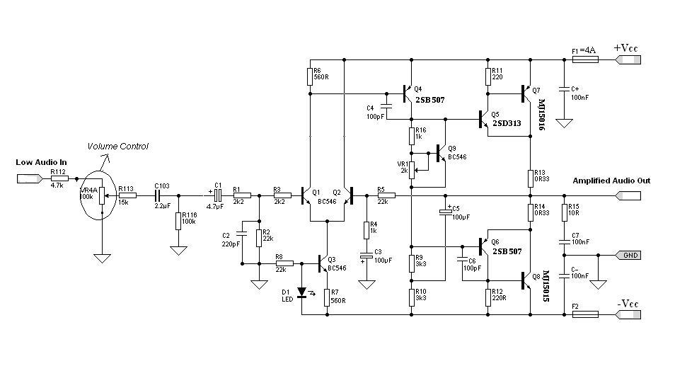
Designing an audio amplifier from scratch using discrete components is an engaging task, as it enables users to create amplifiers that meet diverse requirements. Audio amplifiers can enhance low-level sounds from mobile devices, making them louder and more vibrant....
This indicator can be used, or see if your speakers can be damaged by the noise power. With P1 you can set the limit to which D1 LED lights. The pot is 100k here, you can even experiment with...
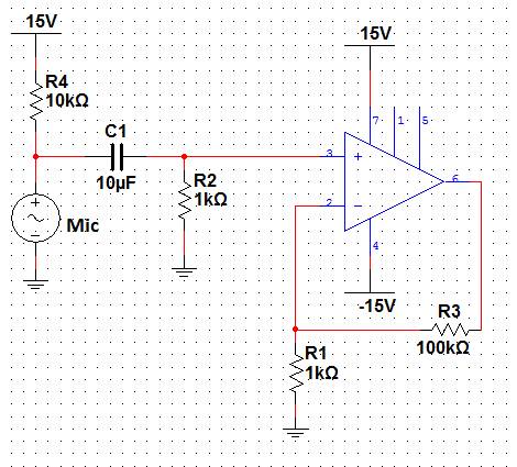
This lab will demonstrate the theory and operation of non-inverting amplifiers as well as their practical application to amplify the signal of a microphone. A non-inverting amplifier will be constructed to increase the output signal of a microphone, which...
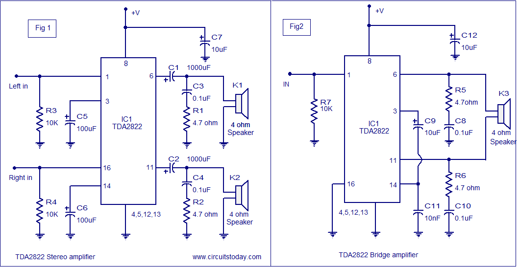
The TDA2822 audio amplifier circuit provides 1.35W output into a 4-ohm speaker when powered by a 6V supply. It supports both bridge and stereo modes and operates within a supply voltage range of 3V to 15V, making it suitable...
The circuit is a modified Colpitts oscillator, tuned with MV209 varactor diodes. The resonating inductor and the drain choke are selected by a rotary switch. 1N5711 Schottky diode, D, clamps the maximum positive voltage on the gate of oscillator...
The circuit serves as a foundational design, requiring experimentation for specific applications. In popular microwave bands, local oscillators (LOs) are typically generated using overtone crystal oscillators followed by multipliers. A table presents the standard LO frequencies for narrowband segments,...