
Stage VI Mixer
The described setup involves configuring a Software Defined Radio (SDR) system, specifically using the Rocky software to analyze signals. The process begins by adjusting the local oscillator frequency to the desired center frequency of 7.046 MHz. This is a critical step, as the local oscillator frequency determines the operational bandwidth and the range of frequencies the SDR can effectively process.
Once the local oscillator is set, the next step involves preparing a signal source. A low-power signal at 7.059 KHz is generated and transmitted into a dummy load. The purpose of using a dummy load is to prevent signal reflection and ensure that the test environment is controlled. The signal source should be loosely coupled to the board with a short wire, allowing for minimal interference while still enabling signal injection.
For the spectrum analysis, the signal source can be programmed to sweep frequencies around the center frequency. This sweeping action allows for a visual representation of the signal spectrum on Rocky's display, facilitating the identification of signal characteristics and any potential interference within the specified bandwidth.
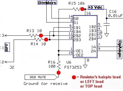
The RF signal injection at the ANT and RTN pads is a crucial phase in the testing process. By injecting a signal of about 10 mV RMS, the system can assess how well the SDR processes the input signal. The selected frequency for injection should be close to the center frequency, ensuring that the output reflects the intended audio frequency difference. The output at the R and T pads should yield an audio frequency signal of approximately 5 V p-p, indicating successful signal processing by the SDR.
Completion of the mixer tests and installation of any additional hardware marks the transition to practical operation. The final test phase, utilizing Rocky as the SDR software, confirms that the system is functioning correctly and is capable of receiving and processing signals as intended. This comprehensive setup and testing procedure ensures that the SDR is fully operational and ready for real-world applications.In the "DSP" tab`s "Local Oscillator" section, click on the button marked "Single Band" and type in the desired center frequency (7046000). This sets Rocky`s center frequency at 7. 046 MHz. Set up your transceiver (or other signal source) to transmit a low power signal at 7. 059 KHz into a dummy load and loosely couple it to the board with a short wire If your signal source can sweep the frequency, observe Rocky`s spectrum display as the generator sweeps through the "chunk" of bandwidth centered on the center frequency. Inject an RF signal of about 10 mV RMS at the ANT and RTN pads on the right side on the main board. The signal should be a few kHz either side of the selected center frequency (e. g. , inject a 7. 059 MHz signal for a center frequency of 7. 046 MHz. Look for the output at the R (ring) and T (tip) pads on the left side of the main board. It should be an audio frequency representing the difference between the injected signal and the selected center frequency and it should be approximately 5 V p-p.
Once the mixer tests are completed and the extra hardware is installed, you are ready to take the radio for a spin. This final test will use Rocky as the SDR Software. This test assumes you have the following: 🔗 External reference
Related Circuits
This circuit resembles an LED clock, utilizing 12 neon indicator lamps in place of LEDs. It operates on two high-capacity nickel-cadmium (Ni-Cad) cells providing 2.5 volts, allowing sustained operation for several weeks. The high voltage (70 volts) required for...
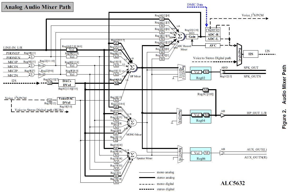
These netbooks utilize the ALC5632 audio codec along with a mixer IC, which features a number of knobs and switches. Most of these controls can be directly manipulated using alsamixer, GNOME Volume Control, and other applications that interface with...
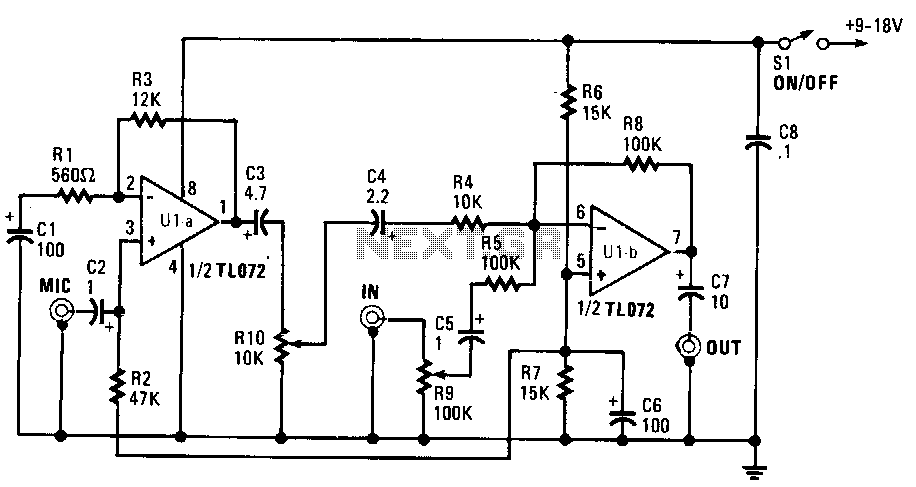
This mixer is constructed using a TL072 dual BiFET operational amplifier featuring a JFET input stage and can be powered by a single-ended power supply ranging from 9 to 18 volts. The microphone input is capacitively coupled to the...
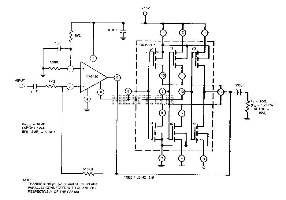
This circuit effectively enhances the current-sourcing and current-sinking capabilities of the CA3130 BiMOS operational amplifier. This configuration increases the current-handling capacity of the CA3130 output stage by approximately 2.5 times. The circuit described is designed to augment the output performance...
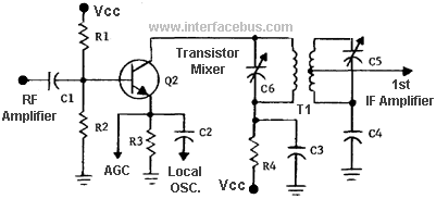
In general terms, a mixer is any circuit that combines two or more circuits or signals into a common output. A more specific definition describes a mixer as a nonlinear circuit that accepts two different frequencies (F1 and F2)...
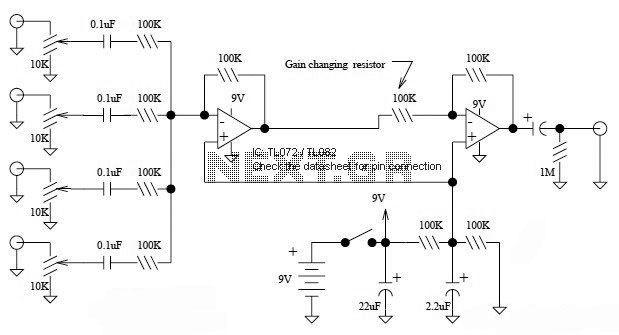
This is a simple mixer featuring four inputs and two operational amplifiers (op-amps). It is designed for mixing microphone signals or effects outputs. The overall gain from input to output is unity when the potentiometer associated with the input...