
LED Flasher Circuit Using 555 Timer IC Schematic Diagram

The parts list for this simple LED project includes the following components:
1. 555 Timer IC
2. Resistors (R1, R2)
3. Trimpot (Potentiometer)
4. Capacitor (C2)
5. Two LEDs
6. Power supply (5 V to 15 V DC)
In this LED flasher circuit, the 555 timer operates in astable mode, generating a continuous square wave output. The configuration allows for a self-oscillating circuit, where the timing components (R1, R2, and C2) determine the frequency and duty cycle of the output signal. The LEDs are connected in a complementary fashion, ensuring that only one LED is illuminated at any given time, creating a flashing effect.
The charging and discharging process of capacitor C2 is crucial for the operation of the circuit. As C2 charges through the resistors, it reaches a threshold voltage of 2/3 VCC, at which point the 555 timer toggles its output state. The discharge occurs through R2 and the trimpot, allowing C2 to drop to 1/3 VCC before the cycle repeats. By adjusting the trimpot, the resistance in the charging path can be varied, effectively changing the timing intervals and thus the flashing frequency of the LEDs.
This simple yet effective LED flasher circuit can serve various applications, including visual indicators, teaching aids for electronics students, or decorative lighting effects. The straightforward design and minimal component count make it an excellent project for beginners in electronics.This is a simple LED flasher project that uses a common 555 timer IC for its operation. It is configured as an astable mode which means that its output is a square wave oscillator. Two LEDs are connected to its output in such a way that when one LED is ON, the other LED will turn OFF. It uses only 10 simple parts that are easily available at any e lectronic shops. Capacitor C2 charges exponentially through resistors R1, R2 and the resistance of the trimpot. When C2 has charged to about 2/3 VCC it stops charging and it discharges to about 1/3 VCC through R2 and the trimpot resistance via pin 7. This is the standard operation of a 555 timer. When a Vcc of 5 V to 15 V DC is applied to the circuit, the LED will start to flash. The frequency of the flashing can be changed by varying the resistance of the potentiometer or trimpot.
Parts List The parts list of the simple LED project is as shown below. You are reading the Circuits of LED Flasher Circuit Using 555 Timer IC And this circuit permalink url it is 🔗 External reference
Related Circuits
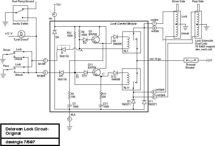
This document discusses the enhancement of a lock control module, providing instructions and photographs for upgrading the module to minimize its standby current consumption, thereby extending battery life. It is assumed that the user possesses a basic level of...
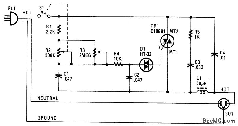
The following circuit illustrates a Phase Controlled Triac (HT-32) Circuit Diagram. Features include a simple circuit design, and bilateral triggering diacs provide a... The Phase Controlled Triac circuit, utilizing the HT-32 component, is designed for applications requiring precise control of...
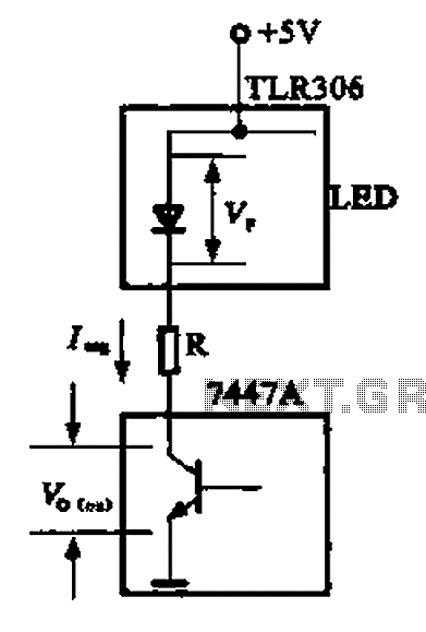
The circuit depicted is a large high-brightness LED driver designed to provide sufficient drive current, utilizing integrated circuits such as the 7447A or 74247. The digital display tube consists of eight light-emitting diodes, with seven dedicated to the digital...
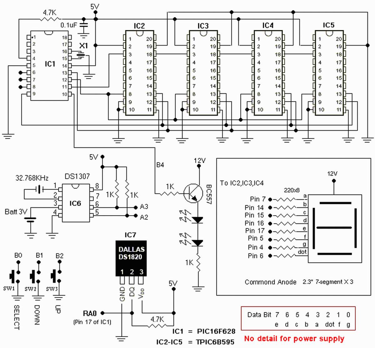
The clock is based on the PIC16F877 microcontroller from Microchip Technology Inc., which performs all of the logic necessary to decode the MSF signal and display the time on twelve 7-segment displays. The circuit design incorporates the PIC16F877 microcontroller, a...

More: The input data contains a brief description with no additional context or information provided. In the realm of electronics, a circuit schematic typically serves as a visual representation of an electrical circuit. It illustrates the various components such...

This is a switch-selectable dual output version of a previous design from 2007, utilizing a field-programmed EPROM to generate two versions of the ringing sequence. The AC mains voltage is stepped down to approximately 10 V AC and then...