
Stand Alone 600mA Li-ion Battery Charger
The EUP8054 linear charger is designed to facilitate efficient charging of single-cell Li-ion batteries while ensuring safety and reliability. The integration of thermal feedback mechanisms allows for the safe operation of the charger under varying load conditions and ambient temperatures. The fixed output voltage of 4.2V is crucial for maintaining the health and longevity of Li-ion batteries, preventing overcharging which can lead to thermal runaway or battery failure.
The ability to adjust the charge current through an external resistor provides flexibility for different battery capacities, accommodating a range of applications from low-power devices to more demanding portable electronics. The trickle charge mode is particularly beneficial for deeply discharged batteries, allowing for a gradual increase in voltage, thus protecting the battery from damage.
The low standby current draw of less than 2µA when not in use is a significant advantage, enhancing the overall energy efficiency of the device. This feature is particularly important in battery-powered applications where power conservation is critical.
The inclusion of a charging status indicator using an LED enhances user experience by providing a visual cue of the charging state, which can be particularly useful in portable applications where users may not have direct access to the device's charging circuitry.
In conclusion, the EUP8054 charger controller offers a robust solution for managing the charging of single-cell Li-ion batteries, with features that cater to safety, efficiency, and user convenience, making it an excellent choice for a wide variety of portable electronic devices.A constant-current/constant-voltage linear charger for single-cell lithium-ion (li-ion) can be constructed using only a tiny battery charger controller chip EUP8054 and a few passive components. This tiny integrated circuit chip is suitable for various portable devices. This controller chip is also compatible with USB power specification, ideal f or charging the battery when the device is plugged to USB port. Here is the circuit`s schematic diagram in the minimum system application. External sense resistor is not needed since the MOSFET internal architecture has accommodated this function. During high power operation or high temperature, a thermal feedback regulates the charge current to limit the die temperature.
The charge voltage is fiexd at 4. 2V, and the charge current is adjustable via an external resistor. The cotroller chip automatically terminate the cahrging cycle when the charging current drops to 1/10th of nominal programmed value after the final float voltage is reached. The controller automatically enter low current state when the input supply is removed, draw less than 2uA current from the battery.
A charge cycle begins when the voltage at the VCC pin rises above the UVLO threshold level and a 1% program resistor is connected from the PROG pin to ground or when a battery is connected to the charger output. If the BAT pin is less than 2. 9V, the charger enters trickle charge mode. In this mode, the EUP8054 supplies approximately 1/10 the programmed charge current to bring the battery voltage up to a safe level for full current charging.
(Note: The EUP8054X does not include this trickle charge feature). When the BAT pin voltage rises above 2. 9V, the charger enters constant-current mode, where the programmed charge current is supplied to the battery. When the BAT pin approaches the final float voltage (4. 2V), the EUP8054 enters constant-voltage mode and the charge current begins to decrease. When the charge current drops to 1/10 of the programmed value, the charge cycle ends. To set the charging current (Ic), select the resitor connected to pin 5, R=(1000)/Ic, or Ic=1000/R. Using the component value as shown in the schematic diagram, the charging current is set to 1000/1650=0, 606A or about 600mA.
Using different resistor value, up to 800mA can be handled by this charger controller. A charging status can be added by connecting a LED in series with 330R resistor, connected across Vcc and pin 1 of the charger controller chip. The LED will turn on when the charging is active, and off when the charging ends. [Circuit`s schematic diagram source: Eutech Microelectronics EUP8054 datasheet] 🔗 External reference
Related Circuits
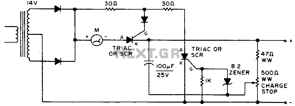
Adjust by setting the 500-ohm resistor while attached to a fully charged battery. The circuit involves a 500-ohm resistor that is to be adjusted while it remains connected to a fully charged battery. This setup is typically used in applications...
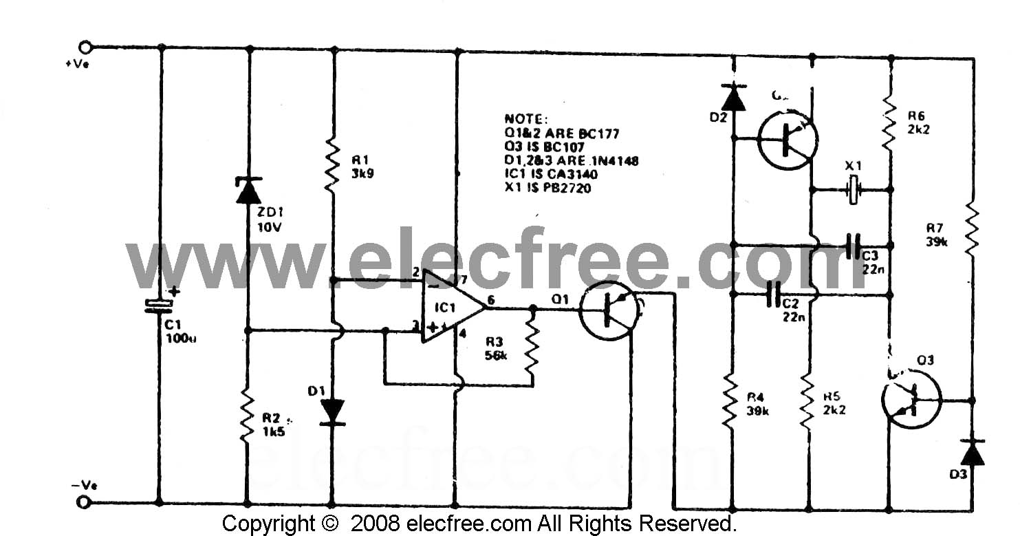
To check the battery in a car, an easy circuit utilizing the IC CA3140 and a transistor is employed. The voltage level of an automobile battery is influenced by many factors, and if it is high... The circuit for checking...
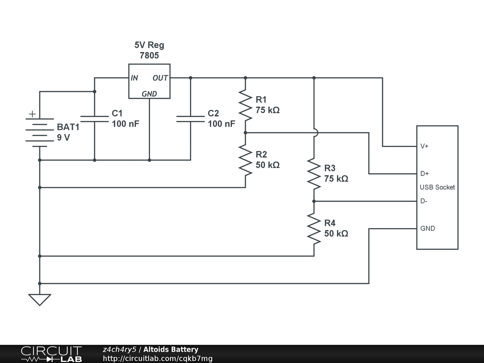
Instructions for creating a battery pack for Apple devices powered by standard alkaline batteries are provided. This overview outlines the circuit design for the battery pack, with detailed casing instructions to follow in a subsequent section. Note: When soldering...
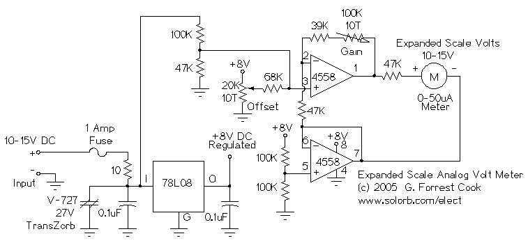
This circuit is used to measure the voltage on a 12V (nominal) lead acid rechargeable battery system. It was specifically designed for use in solar powered systems, but is general enough that it can be used for automotive or...
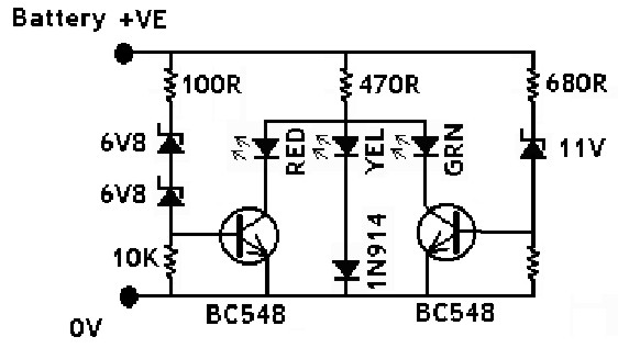
The IN914 (small glass diode) and the zener diodes have bands on their bodies that must be oriented according to the diagram provided. The bands are located at the cathode end of the diodes. A magnifying glass can assist...
The circuit is capable of supplying either a trickle (50 mA) or high-current (1-A) charge. You can select either charging method or an automatic mode that will first trickle charge a battery if it is particularly low before switching...
Warning: include(partials/cookie-banner.php): Failed to open stream: Permission denied in /var/www/html/nextgr/view-circuit.php on line 713
Warning: include(): Failed opening 'partials/cookie-banner.php' for inclusion (include_path='.:/usr/share/php') in /var/www/html/nextgr/view-circuit.php on line 713