
Stepper Motor Circuits
The operation of stepper motors relies heavily on precise control of the winding energization sequence. The driver circuit, typically composed of transistors or integrated circuits, amplifies the control signals and ensures that the correct winding is energized at the appropriate time. For unipolar motors, the circuit configuration allows for a straightforward connection to the center tap, while bipolar motors require a more complex H-bridge arrangement to manage the direction of current flow through the windings. The inclusion of diodes in the circuit is crucial for protecting components from back EMF generated when the inductive windings are de-energized.
The choice of switching technology can significantly influence the performance and efficiency of the driver circuit. Power Darlington transistors offer high current gain, making them suitable for applications requiring substantial current, while power FETs provide lower on-resistance and faster switching speeds, which can enhance overall system responsiveness.
When implementing a driver circuit for a stepper motor, considerations such as the maximum current rating, thermal management, and switching frequency must be addressed to ensure reliable operation. Integrated circuits like the DS2003 and L297 provide a compact solution for controlling stepper motors, simplifying the design process while offering built-in features for managing speed and direction. The L297, in particular, facilitates the control of both unipolar and bipolar motors, making it a versatile choice for various applications.
In summary, stepper motor control requires a well-designed driver circuit that incorporates protective measures against voltage spikes, utilizes appropriate switching technology, and can be efficiently managed using dedicated indexer circuits or microcontrollers. The integration of these components into a cohesive schematic will enable precise control of stepper motors for a wide range of applications.To control a stepper motor, you have to energize each winding individually in a specific and timed order. The energizing is accomplished by a driver circuit (an amplifier). The timing is performed by an indexer circuit and the objective (go forward, go backward, brake, coast, etc.
) is controlled by some external user interface, such as a computer or joystick. The figure below shows this process. The circuits for driving unipolar and bipolar stepper motors differ because bipolar stepper motors don`t have a "center tap. " However, it is possible to use bipolar drivers to drive unipolar steppers after some small modifications.
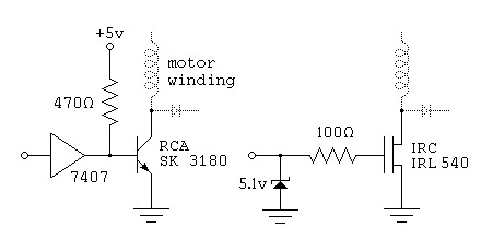
Care must be taken in the driver circuit to protect against voltage spikes. Because the motor windings are inductors, switching off the power to the winding produces a short burst of voltage. To protect against this, always put a diode in parallel with the winding, making sure the diode can handle the winding current.
This is shown in the following figure. For the switches, any kind of switching technology can be used. The following figure shows two such switches. The first one uses a power darlington transistor and the second one uses a power field effect transistor. For driving a full stepper motor, with multiple coils, you can either build each of the above circuits individually, or you can use a integrated chip.
One such chip is the DS2003, which is a darlington array, and is shown below. This chip can be used when the total current to each winding is less than 500 milliamps. Bipolar stepper drivers use H-bridges to energize the windings of the motor. H-bridges allow you to choose the direction of the current through the winding. Using an H-bridge configuration, there are four transistors for each winding as shown in the first figure below. However, most of the time they are prewired together so that only two inputs are needed. This makes generating pulses easier and also serves to protect against short circuits. This circuit is shown in the second figure below. You should be able to drive a bipolar motor with a unipolar motor circuit. The only difference is that there are no center winding taps to connect to the power source. Somebody correct me There are many methods of producing the index pulses needed to drive stepper motors.
This can either be done using a microprocessor or an integrated circuit. The calculations will most likely be so burdensome that the microprocessor would be unable to do any other calculations while producing the pulse trains. However, there are many cheap microcontrollers available these days and they could be used as dedicated indexers.
The L297 is a 20-pin DIP chip that was designed specifically to control either unipolar or bipolar stepper motors. It will control two H-bridges to power two windings. Its inputs control the speed and direction of the motor. The diagram below shows the typical setup of the circuit. The A and B outputs would correspond to the X and Y inputs on the H-bridge of the first winding (see above).
Likewise, the C and D outputs would correspond to the X and Y inputs on the second winding. 🔗 External reference
Related Circuits
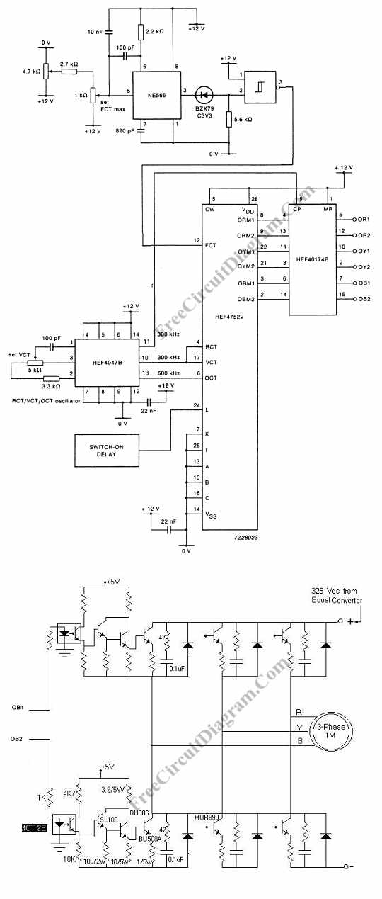
Controlling the speed of a three-phase AC motor is achieved by regulating the frequency of the power supply, as the motor operates in synchronization with the line. To control the speed of a three-phase AC motor, it is essential to...
The challenge is to control the speed of the motor. One approach is to use a plane, radio, and speed control integrated with the motor, but this is not ideal. Alternatively, mounting the motor on a bench and directly...
Physical motion of some form helps differentiate a robot from a computer. It would be nice if a motor could be attached directly to a chip that controlled the movement. But, most chips can't pass enough current or voltage...
Activated this and inadvertently destroyed several 2N3055 transistors by shorting the emitters to ground. In all cases, the transistors opened up, and no damage to the emitter occurred in any transistor. The alternative circuit in Figure 2 will provide...
Traditional control methods for fan power equipment involve manual or relay control, which often leads to issues of poor reliability and flexibility. For instance, when the motor capacity is large, the startup process can be prolonged, resulting in high...
This circuit utilizes a single 555 Timer IC and a small transformer to generate high voltage for testing zener diodes with voltage ratings up to 50VDC. The 555 timer operates in astable mode, with the output at pin 3...
Warning: include(partials/cookie-banner.php): Failed to open stream: Permission denied in /var/www/html/nextgr/view-circuit.php on line 713
Warning: include(): Failed opening 'partials/cookie-banner.php' for inclusion (include_path='.:/usr/share/php') in /var/www/html/nextgr/view-circuit.php on line 713