
Adjustable Voltage motor controller
The Adjustable Voltage Control unit is designed for precise motor speed regulation, which is crucial for applications requiring gradual acceleration and deceleration. The use of VR1 as a voltage divider allows for fine-tuning of the control signal to Q5, ensuring smooth transitions in motor speed. The parallel configuration of Q1, Q2, Q3, and Q4 enables increased current handling capacity while maintaining a balanced load distribution, which is essential for the longevity of the transistors and the overall system.
The inclusion of one-ohm resistors at the output of the 3055 transistors serves to mitigate discrepancies in current sharing among the parallel devices, thereby enhancing reliability. The 12-volt regulator's function is vital for providing stable operation of ancillary components, such as the fan, which is critical in managing thermal conditions within the circuit. The careful placement of the regulator on the heatsink's exhaust side is a strategic design choice aimed at optimizing thermal dissipation.
Heat management is a significant consideration in this design, as excessive heat can lead to premature failure of the transistors. The noted voltage drop characteristics illustrate the importance of accounting for power losses in the circuit design, particularly when high current loads are expected. By utilizing two battery packs in series, the design effectively addresses the challenge of maintaining adequate voltage levels under load conditions, ensuring that the motor receives sufficient power for optimal performance. This comprehensive approach to motor control not only enhances functionality but also contributes to the overall durability and efficiency of the system.The problem is how to control the speed of the motor. One way is to use the plane, radio, and speed control with the motor in it. That`s no fun! Mount the motor on the bench and just plug the batteryinto the motor. That`s even worse! It`s hard on the motor and gearbox. To solve the "It`s hard on the motor and gearbox" problem I made myself an Adjustable Voltage Control unit (speed control) so I can slowly bring the motor up to speed. VR1 is used as a voltage divider to drive Q5, Q5 then drives Q1, Q2, Q3, and Q4. As VR1 is turned clockwise the voltage increases on the base of Q5. Q5 then increases the voltage on Q1, Q2, Q3, and Q4. As the base voltage increases on the on Q1, Q2, Q3, and Q4 the voltage will increases to the motor. As Q1, Q2, Q3, and Q4 are used in parallel. 1 ohm resistors are placed on the output of the 3055s to make an attempt to balance the load between them. The 12 volt regulator is used to supply a constant 12 volts to the fan when using voltage above 12 Prototype of the Adjustable Voltage Control.
Note the 12" of 14 awg used for. 1 ohm resistors (red wire). To help keep the 12 volt regulator cool I mounted it on the exhaust side of the Heatsink. (not shown) I have tested this Adjustable Voltage Control and have found that the 3055s generate quit a bit of heat, even mounted to a large fan cooled Heatsink. The voltage drop across the voltage in to voltage out is about. 10 volt per amp or 1 volt for every 10 amps. To make up for the voltage loss I made a series connector to run two battery packs to double the input voltage.
🔗 External reference
Related Circuits
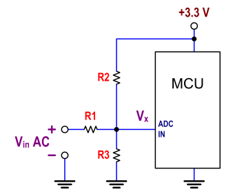
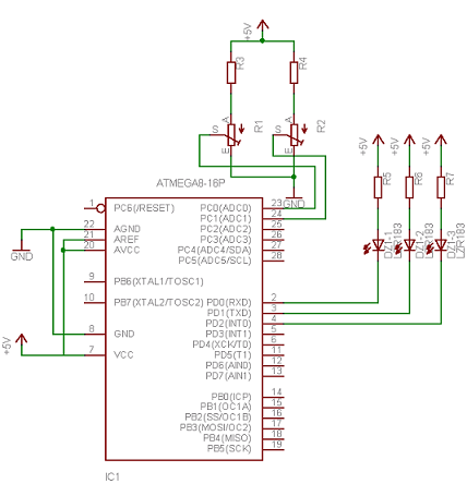
The ATtiny24 microcontroller's ADC is utilized to record an AC signal, which operates within a voltage range of 0 to 3.3V. A precision rectifier is employed to eliminate the negative portion of the signal. The circuit incorporates an LMC6484...
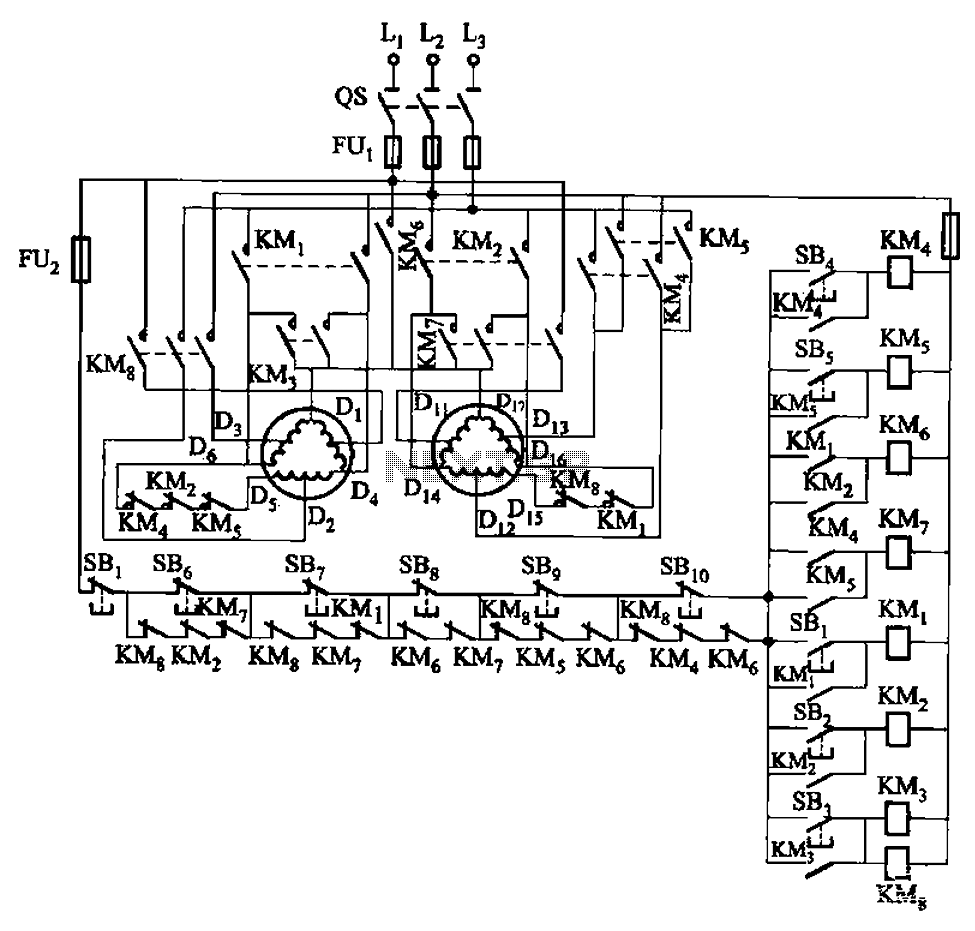
The circuit depicted in Figure 3-120 allows for the control of a motor with a capacity of less than the rated current of 5A by using an intermediate relay instead of a contactor. This circuit enables four forward running...
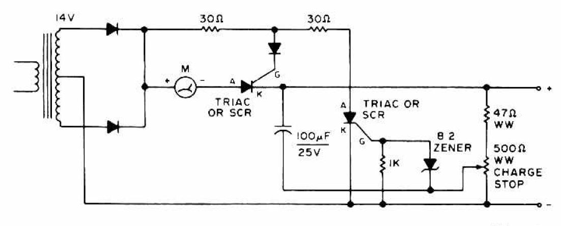
The charging circuit features adjustable voltage output settings, allowing for regulation of the charging voltage supplied to the battery. The use of a potentiometer facilitates precise voltage management, with adjustments possible down to the millivolt range. Refer to the...
The T7024 is a single-supply front-end integrated circuit (IC) specifically designed for applications within the 2.4 GHz to 2.5 GHz frequency band. This front-end configuration includes a Power Amplifier (PA), a Low-Noise Amplifier (LNA), and a switch driver for...
Neural networks are a broad topic. This example demonstrates how to create a basic neural sensor that takes resistive readings from multiple sensors, multiplies them by a weight factor, and then sums the results. The results are compared to...
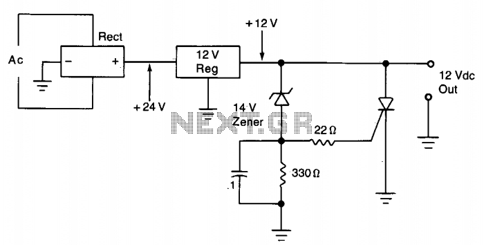
The silicon controlled rectifier (SCR) is designed to handle at least the current provided by the power supply. It is connected in parallel across the 12 V DC output lines but remains inactive until a voltage is applied to...
Warning: include(partials/cookie-banner.php): Failed to open stream: Permission denied in /var/www/html/nextgr/view-circuit.php on line 713
Warning: include(): Failed opening 'partials/cookie-banner.php' for inclusion (include_path='.:/usr/share/php') in /var/www/html/nextgr/view-circuit.php on line 713