
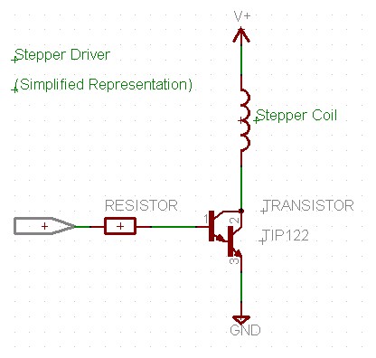
Stepper Motor Control
The described program serves as a control interface for a stepper motor utilizing a microcontroller with a U4x1 architecture. The initialization of the I/O lines is critical for establishing communication between the microcontroller and the stepper motor driver. By configuring the lower and upper port pins of port A, the program effectively segments the control signals into two distinct channels, allowing for more complex motor control strategies.
The "Direction" parameter is vital for determining the rotational orientation of the stepper motor. Depending on the specific wiring configuration of the motor, the actual movement direction can vary. Therefore, it is essential to verify the connections to ensure that the intended direction corresponds with the programmed settings.
The timing control is established through the rate parameter, which is expressed in microsecond increments. This allows for precise control over the stepping frequency of the motor. The example provided indicates a stepping period of 12.8 milliseconds, which translates to a specific number of steps per second, thereby affecting the overall speed of the motor.
The initialization command plays a crucial role in setting the initial position of the stepper motor. By passing the initial step value, the program ensures that the motor starts from a known state, which is particularly important for applications requiring accurate positioning.
Furthermore, the ability to modify both the direction and the rate of the motor while it is running enhances the flexibility of the control system. This feature allows for dynamic adjustments based on real-time feedback or changes in operational requirements, making the system adaptable to various applications, such as robotics, CNC machinery, or automated systems.
In summary, this program provides a robust framework for controlling stepper motors through a microcontroller, utilizing precise timing and directional control to achieve desired motion profiles.This program initializes all of the sixteen io lines of the U4x1 to be outputs. The lower four port pins of port A (A. 0 - A. 3) are "channel 1" when it concerns stepper activity, the upper four port pins of port A (A. 4 - A. 7) are "channel 2" when it concerns stepper activity. "Direction" sets the direction that the stepper motor moves. The actua l direction does depend on the stepper motor wiring. The rate is the period in 128 microsecond increments, "100" in the example is 12. 8 ms between each step. The "Init" command will pass the initial step value to the motor. This is the first positional value. While the motor is running, the direction can be changed and the rate changed. 🔗 External reference
Related Circuits
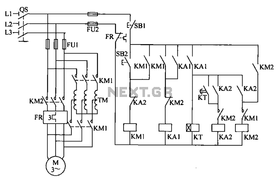
To initiate the system, turn off the power switch, then press the start button SB2. The KM1 contactor is energized, engaging self-locking, and closing the main contacts. The autotransformer TM is connected between the power source and the motor,...
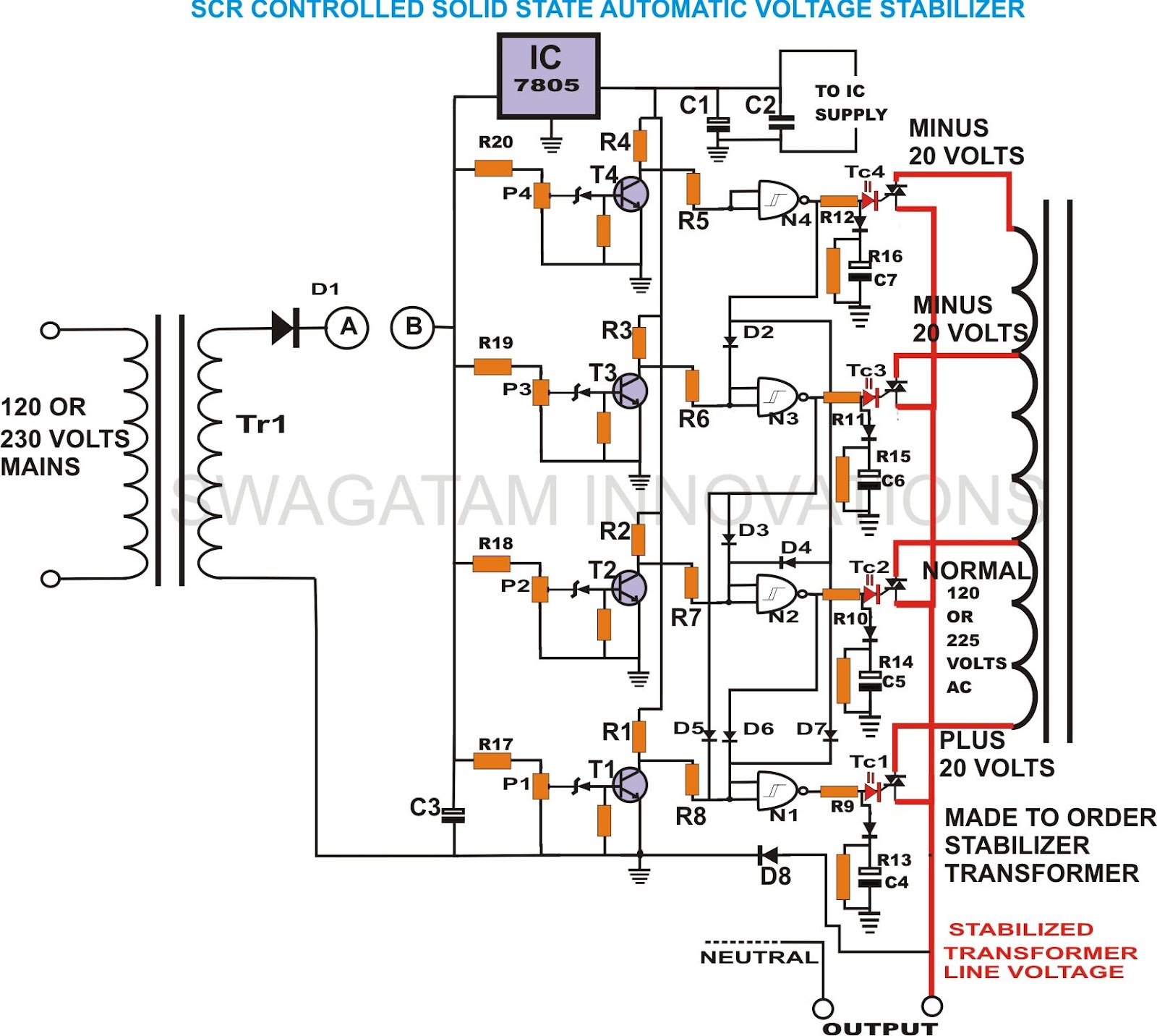
This unique and hard-to-find triac-controlled AC voltage stabilizer circuit has been specifically designed for efficient voltage stabilization. With a solid-state design, the voltage switching transitions are smooth, resulting in minimal wear and tear. The proposed circuit provides four-step voltage...
This SCADA controller is designed for use with distribution (13.2 kV/4.8 kV) substation transformer breaker positions where an automatic throw-over is present. The RTU voltage is 24V DC. The breaker status and lockout relays operate at 48V DC. The SCADA...
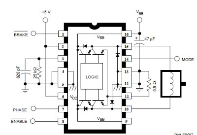
The A3952S integrated circuit, designed by Allegro MicroSystems, can be utilized to create straightforward and effective motor driver circuits. A previous article discussed a basic bipolar stepper motor driver circuit that employs two A3952S circuits. The A3952S is capable...
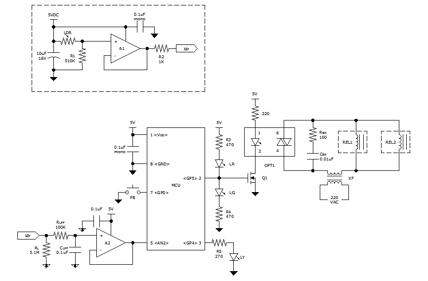
While discussing an all-linear automatic night light circuit, it was mentioned that an MCU-based Automatic Night Light Controller (ANLC) was being tested. The firmware has been tweaked since then. Recently, the sensor was installed outdoors and connected to control...
This volume controller equalizer electronic project utilizes the LM1036 DC tone volume controller, which includes a volume and balance circuit suitable for stereo applications. The LM1036 features an additional control input that facilitates simple loudness compensation. It provides four...