
Stepper Motor Control Circuit

The described circuit involves a stepper motor control system utilizing two LMD18245 motor driver chips, which are designed to facilitate the precise control of current through the coils of the stepper motor. Each LMD18245 is responsible for one coil, allowing for independent control of each phase of the motor. The LMD18245 is a high-performance, dual H-bridge driver that can handle high current loads, making it suitable for driving stepper motors.
In contrast to using a single driver chip, such as the L298, which can control both coils of a stepper motor, the dual chip configuration provides enhanced control and flexibility. This configuration allows for smoother operation and better torque management, as each coil can be driven with tailored current profiles.
For applications requiring the simultaneous control of two stepper motors, the SN754410 is a viable alternative. This chip is capable of managing two two-coil stepper motors, simplifying the design and reducing the number of components needed in the circuit.
The control of current flow direction is critical in stepper motor applications. By reversing the current through the coils, the motor can be made to step in either direction, allowing for precise positioning and movement. The accompanying code, which will be discussed further, outlines the necessary commands and timing sequences to achieve accurate control of the stepper motor's operation.
In summary, the circuit design utilizing two LMD18245 chips for a two-coil stepper motor provides a robust solution for applications requiring detailed control of motor movement. The choice between single and dual driver chips depends on the specific requirements of the motor control application, including performance, complexity, and the number of motors to be controlled. The source code necessary for implementing this control will be available for download, providing a practical resource for developers and engineers working with stepper motors.This circuit is not fun to look at nor is it fun to implement, it takes a bit of effort. Since there are two coils in our stepper motor we`ll use two LMD18245`s to control the current flow through the coils. It is important to note that there are motor control chips like the L298 that offer stepper motor control u
sing only 1 chip. You can also find chips that have the capability of controlling two of these 2 coil stepper motors at once, the SN754410 for example. Next we`ll see take a look at the code necessary to control the stepper motor and see exactly why control of the current flow direction is so important.
Scroll down to the bottom to download the source code file. 🔗 External reference
Related Circuits
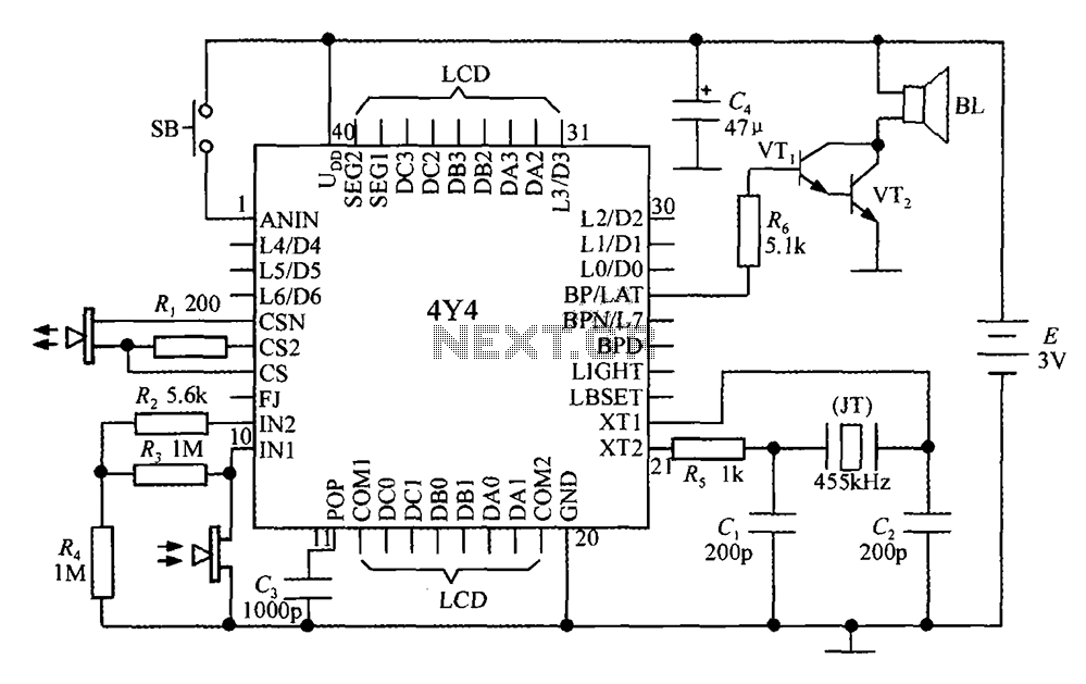
The 4Y4 is a monolithic liquid crystal display rangefinder circuit. The instrument comprises an ultrasonic transmitter, a receiver, an LCD display, buttons, switches, and a buzzer (or speaker). To simplify wiring, the 4Y4 is directly welded to the back...
Converting current into voltage is undesirable for two reasons: first, an impedance is inserted into the measuring line, causing an error; second, amplifier offset voltage is also amplified, leading to a subsequent loss of accuracy. The use of a...
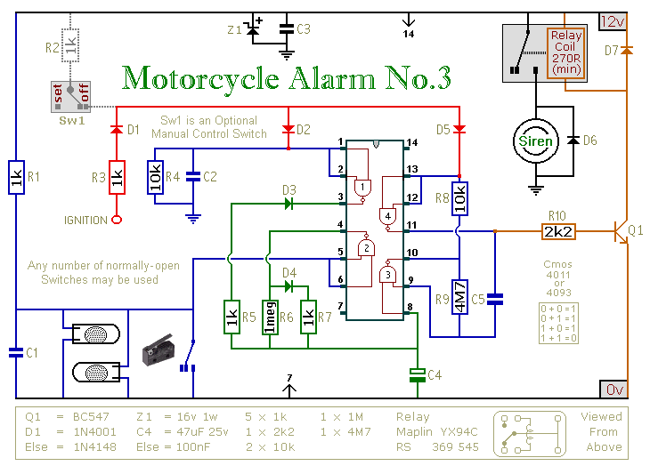
This circuit features an intermittent siren output and automatic reset. It can be operated manually using a key-switch or a hidden switch; but it can also be wired to set itself automatically when you turn-off the ignition. By adding...
This is a small electronic switch that connects a battery to the equipment for a certain amount of time when a push-button is momentarily pressed. The ambient light level has also been considered; when it is dark, the display...
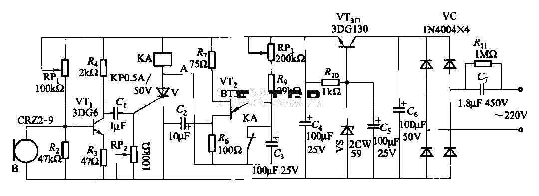
The circuit features voice switches with Figure 2109. It utilizes a single-junction transistor (VT2) and RC components to create a delay. The delay time can be adjusted using the potentiometer (RP3) or the capacitor (C3). The described circuit employs a...
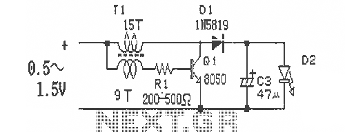
This is a simple and easy-to-build DC-DC driver circuit designed for a single flashlight battery, operating at a parametric voltage of 1.5V. The input current is 90mA, while the light-emitting diode (LED) current is 26mA or higher. The circuit...