
Intelligent Ultrasonic Ranging IC 4Y4 form a monolithic liquid crystal display rangefinder circuit diagram
The 4Y4 rangefinder circuit integrates multiple components to achieve effective distance measurement using ultrasonic technology. The ultrasonic transmitter emits sound waves, which reflect off objects and are received by the ultrasonic receiver. The circuit processes these signals and displays the calculated distance on the LCD screen. The inclusion of buttons and switches allows for user interaction to select measurement modes or reset the device.
The design features a robust power management system, with C4 ensuring stable power supply to prevent fluctuations that could affect measurement accuracy. The use of piezoelectric ceramic filters in the oscillator circuit (455 kHz) is a cost-effective solution that maintains performance while reducing component complexity. The oscillation capacitors (C1 and C2) are crucial for maintaining the frequency stability of the oscillator, which is essential for accurate distance measurements.
The Darlington pair configuration (VT1, VT2) amplifies the signal sufficiently to drive larger speakers, enabling audible feedback for the user. The current limiting resistor (R6) protects the circuit from excessive current that could damage the transistors. The design also allows for adaptability with external circuits, enhancing the functionality of the rangefinder. This feature is particularly beneficial in specialized applications, such as underwater measurements, where increased sensitivity is necessary.
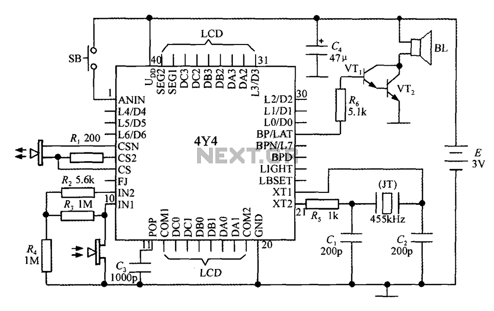
Overall, the 4Y4 circuit exemplifies an efficient and versatile approach to ultrasonic distance measurement, integrating various electronic components to deliver a reliable and user-friendly instrument.4Y4 constituted by a monolithic liquid crystal display rangefinder circuit as shown in FIG. The instrument includes an ultrasonic transmitter, a receiver, LCD display, buttons, switches and a buzzer (or speaker), in order to simplify wiring, 4Y4 welded directly in the back of the display panel LCD. 4Y4 first 2 to 4 feet, 8 feet, 23 feet to 26 feet and 28 to 30 do not. R1 is transmitting circuit current limiting resistor. R2 ~ R4 to amplifier receiving external components. C3 to boot automatically reset capacitor. 455kHz oscillator circuit using an inexpensive piezoelectric ceramic filters instead of quartz (JT), C1 and C2 for the oscillation capacitor.
SB for the push button switch. C4 power supply decoupling capacitors. 4Y4 only drive the piezoelectric ceramic buzzer or micro Xiangqi, in order to drive the speaker, but also need to increase the level ~ Darlington (VT1, VT2) to use as a power amplifier. Current limiting resistor R6 of VT1. According to actual needs, 4Y4 also received external transmission circuit or reception circuit. For example, the sensitivity of the ultrasonic probe waterproof seal is only 1/10 of ordinary probe can only measure without external transceiver at 50cm distance, the increased expansion circuit can improve the reception sensitivity to meet the special requirements of underwater ranging.
Related Circuits
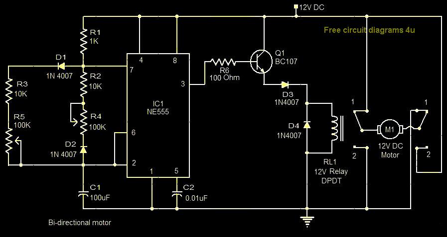
This circuit illustrates a bi-directional motor control circuit utilizing the NE555 integrated circuit (IC). Features include a 12V DC power supply, with the IC employed to control relay RL1. The bi-directional motor control circuit designed with the NE555 IC allows...
The primary components of this doorbell circuit include two NE555 timer integrated circuits (ICs). When the switch S1 is pressed momentarily, the loudspeaker emits a bell tone for the duration determined by the time period of the monostable multivibrator...
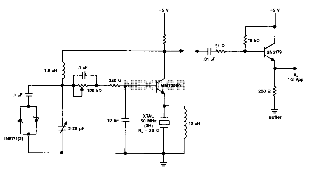
The diagram illustrates a 50 MHz oscillator functioning at its third harmonic. The collector load resistor R1 has been increased due to the rise in the quartz crystal's internal series resistance Rs, which escalates with frequency in the VHF...
Figure A illustrates the schematic of a microstrip single-stage RF amplifier. This amplifier utilizes the M/A-Com LF2810A MOSFET, which is rated for 10 watts and operates at 28 volts, but it delivers sufficient gain for this application at a...
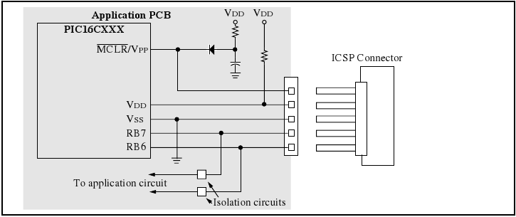
The programmer utilizes a serial signaling scheme to program the chip while it is in-circuit. The signaling is transmitted through the programming clock (PGC or ICSPCLK) and the programming data (PGD or ICSPDAT) pins. Additionally, the MCLR/VPP pin serves...
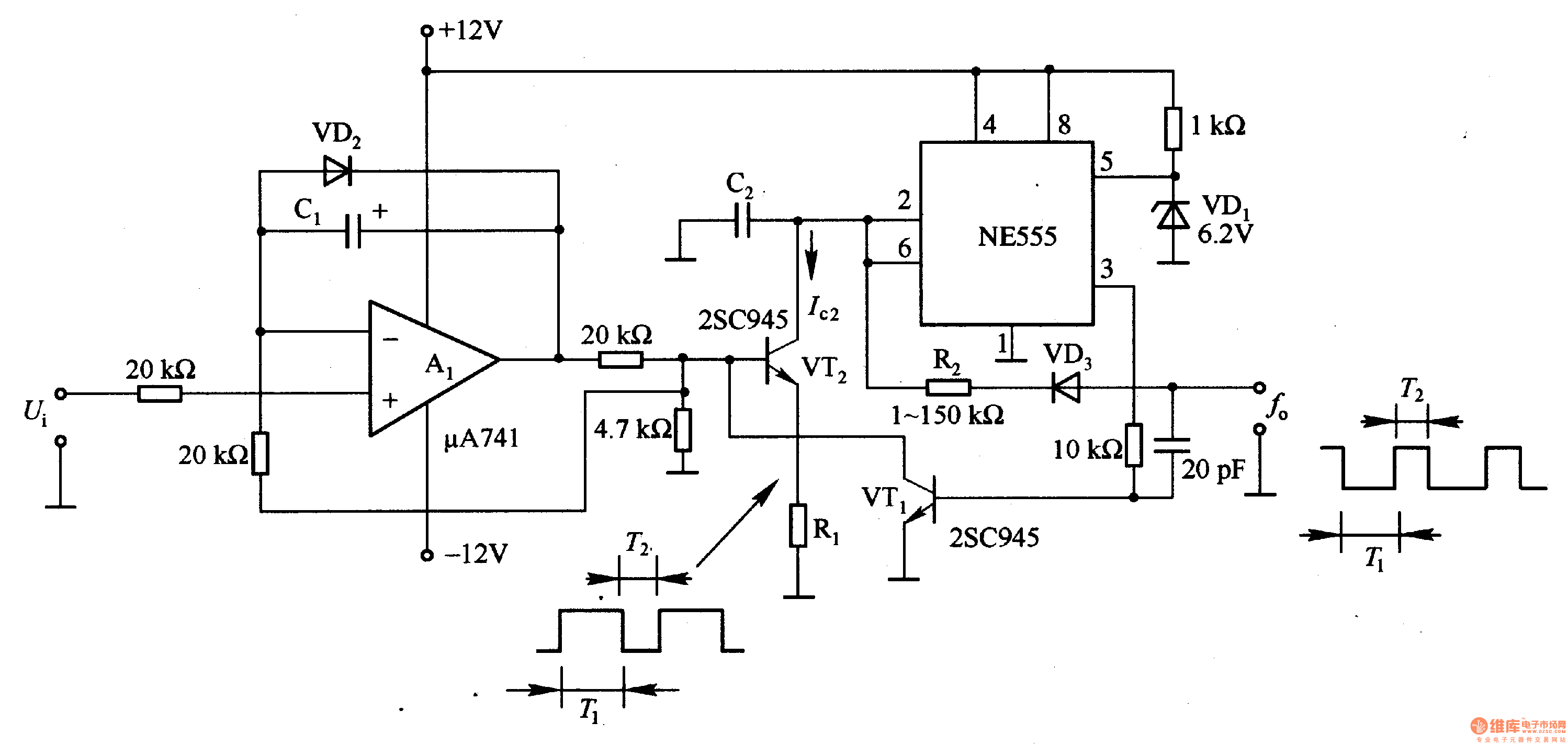
In the circuit, the oscillation frequency of the NE555 is controlled by VT2. When the output at pin 3 is low (during the T1 period), VT1 stops conducting, and VT2 begins to conduct with a current Ic2 flowing through...