
Three thyristor switch voice lighting circuits
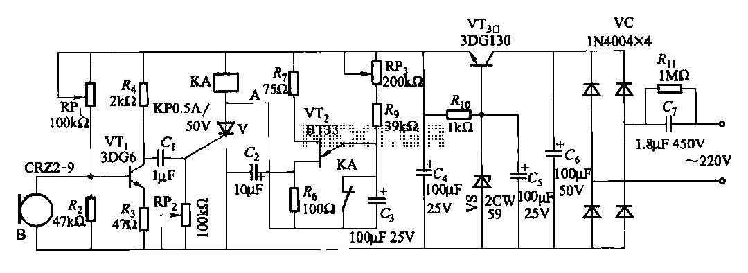
The described circuit employs a single-junction transistor (VT2) as the primary switching element, which is pivotal in controlling the voice activation mechanism. The inclusion of resistive (R) and capacitive (C) components forms an RC delay circuit, which is essential for managing the timing of the voice switch activation.
The adjustment potentiometer (RP3) allows for fine-tuning of the delay time, providing flexibility in operation according to specific application requirements. By altering the resistance, the charge time of the capacitor (C3) can be modified, thus changing the time it takes for the circuit to respond after the voice activation signal is received.
The capacitor (C3) plays a crucial role in determining the delay duration; a larger capacitance will result in a longer delay, while a smaller capacitance will yield a shorter delay. This adjustable delay feature is particularly useful in applications where precise timing is critical, such as in automated voice-activated systems or in scenarios where a delay is necessary to prevent false triggering from ambient noise.
Overall, the combination of the single-junction transistor, RC components, and adjustable elements provides a versatile and effective solution for implementing voice-activated switching in electronic circuits.Features voice switches with Figure 2109. From single-junction transistor VT2 and RC components delay the circuit. Adjustment potentiometer RP3 or capacity capacitor C3 can cha nge the delay time.
Related Circuits
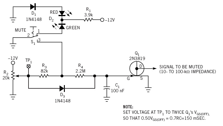
This simple circuit is a line-level audio signal muting switch based on a soft-action power on/off process. When the S1 switch is closed, R4, C1, and Q4 JFET are activated to mute the audio signal. The circuit operates by utilizing...
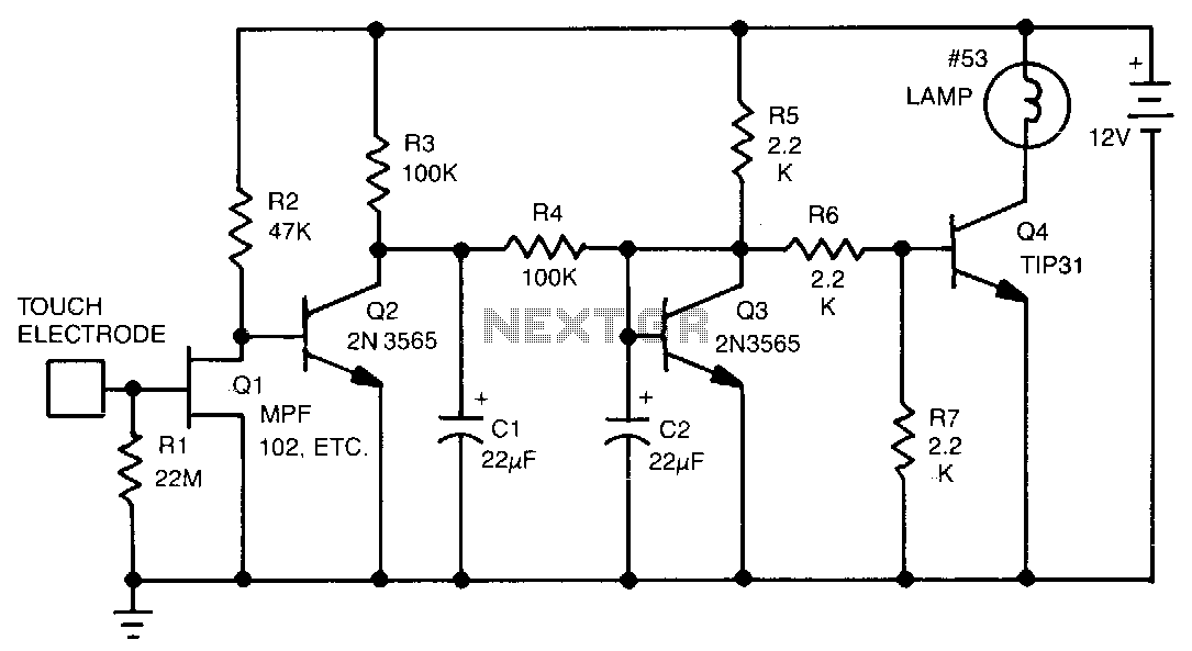
This touch-activated switch remains in the 'on' state as long as the user's finger is in contact with the touch plate. Resistor R1 establishes a high input impedance of 22 MΩ. Transistor Q1 detects stray signals that are coupled...
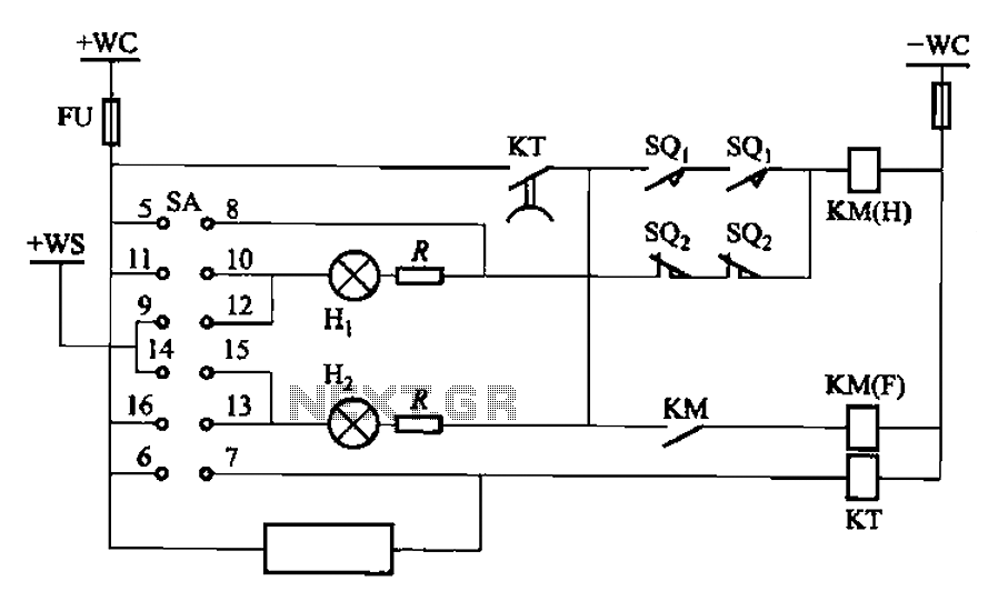
The BT9404 is a de-excitation type switch utilized with CJ4-S contactors and JT3-21/3-type electromagnetic relays. The control circuit is depicted in Figure 7-55. The KM contactors used are CJ4-S, while the time relay is the JT3-21/3. The SA component...
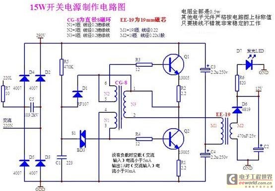
A daily switching power supply primarily provides direct current (DC) power to electronic devices. The required DC voltage for electronic devices typically ranges from several volts to over ten volts, while the input voltage from the mains supply is...
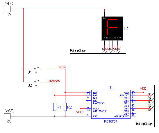
National Instruments Multisim now features microcontroller unit co-simulation capabilities, enabling the inclusion of a microcontroller, programmed in assembly or C code, within SPICE-modeled circuits. The MCU functionality in Multisim allows students, educators, and professional users to program MCUs in...
A switching power supply with an output voltage significantly lower than its input voltage exhibits an interesting characteristic: the current drawn by the supply is less than its output current. However, the input power (UI) is greater than the...
Warning: include(partials/cookie-banner.php): Failed to open stream: Permission denied in /var/www/html/nextgr/view-circuit.php on line 713
Warning: include(): Failed opening 'partials/cookie-banner.php' for inclusion (include_path='.:/usr/share/php') in /var/www/html/nextgr/view-circuit.php on line 713