
Dremel Speed Controller
The described setup utilizes a Dremel drill with a mini drill-chuck mounted on a stand, specifically designed for drilling circuit boards. The inherent limitation of the Dremel drill is its poor performance at low speeds, which is exacerbated by a malfunctioning internal speed controller. To address this issue, a workaround was implemented by bypassing the faulty controller and connecting the drill to a regulated 24-volt DC power supply. However, simply reducing the voltage to slow down the motor leads to stalling, particularly when engaging with the material being drilled.
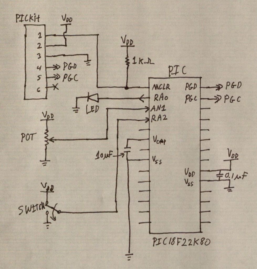
To enhance the motor control under varying load conditions, a circuit employing a logic-level N-channel Field Effect Transistor (FET) was developed. This FET is driven by a microcontroller, specifically a PIC (Peripheral Interface Controller), which generates a variable Pulse Width Modulation (PWM) signal. The PWM signal effectively controls the power supplied to the motor, allowing for fine-tuning of the speed.
Current sensing is accomplished through a 0.5-ohm resistor connected to ground. This resistor is strategically placed in the circuit to measure the voltage drop across it, which is directly proportional to the motor current. The sensing occurs during the PWM power pulse, ensuring that any variations in voltage are attributable solely to changes in motor current. The sensed voltage is then filtered to remove noise and is fed into an Analog-to-Digital (A/D) input of the PIC. As the voltage indicative of motor current increases, the PIC responds by increasing the pulse width of the PWM signal, thereby supplying more power to the motor and preventing stalling.
A momentary push button switch is integrated into the design to provide a simple means of turning the power on and off, facilitating the process of changing drill bits without the need to disconnect the power supply. The entire assembly is securely attached to the side of the stand using double-stick tape, ensuring stability and accessibility during operation.
The performance of this modified Dremel drill setup is satisfactory, though it may be further improved with a higher supply voltage, in the range of 30 to 35 volts, to enhance torque and speed control capabilities. This circuit design exemplifies a practical solution for achieving variable speed control in power tools, particularly in applications requiring precision drilling in electronic circuit boards.The Dremel drill fitted with a mini drill-chuck on a stand is a great setup for drilling circuit boards. The problem is that it does not do low speeds very well. My unit had a failed internal speed controller, so I just wired around it and connected it to a regulated 24 volt DC supply.
This worked OK, but I would like a slower speed when drilling boards. Slowing down with a lower voltage, however, causes it to stall out completly when it begins drilling. What I needed was a circuit to actually increase power to the motor under increasing load. The circuit at right uses a logi-level N-channel FET driven directly by the PIC. The PIC creates a variable PWM signal to power the motor. Motor current is sensed using a combined 0.5 ohm resitance to ground. Since this voltage is only sensed during the power pulse, and the external voltage feed is well regulated, all of the change in the voltage is due to motor current. This signal is filtered and fed to an A/D input. As the voltage here increases, the PIC increases the power to the motor by increasing the pulse width.
The momentary push button is used to switch the power on and off for ease in changing drill bits. The whole assembly is fastened to the side of the stand with double-stick tape. As it is, this unit performs quite well. It would work a bit better with maybe 30 or 35 volts feeding the system. 🔗 External reference
Related Circuits
Power Saving Using Time Operated Electrical Appliance Controlling System is a reliable circuit that takes over the task of switching on/off the electrical devices with respect to time. This project replaces the manual switching. It has an inbuilt real-time...

High brightness (HB) and super HB LEDs are utilized in LCD TFT backlighting for high-end televisions, industrial lighting, and projectors. A notable application is in instrument panel backlighting, interior lighting, and brake lights of various vehicles. Luxury automobile manufacturers...
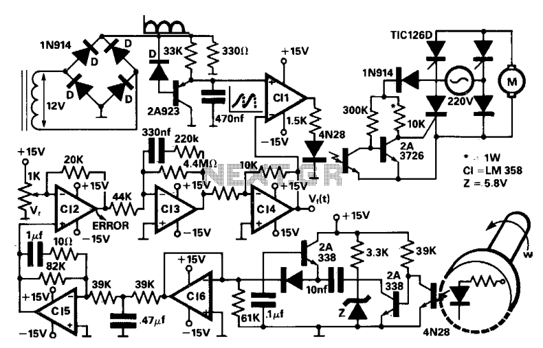
A four thyristor controlled bridge is utilized for operation in two quadrants of the torque-speed characteristics. In the trigger circuits, conventional pulse transformers are substituted with self-biased circuits, which reduce gate power consumption and enhance noise immunity. Electrical isolation...
PIC microcontrollers are a highly useful and versatile component for various electronic projects. They are affordable and readily available. PIC microcontrollers are embedded systems that serve as the central control unit in a wide range of electronic applications. Their architecture...
During summer nights, the temperature is initially quite high. As time passes, the temperature starts dropping. Also, after a person falls asleep, the metabolic rate of one's body decreases. Thus, initially the fan/cooler needs to be run at full...
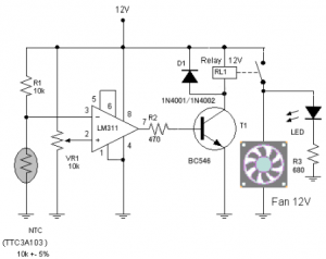
The circuit schematic diagram of a fan speed control system that activates only when necessary. When the transistor heats up, the fan will automatically turn on. The fan speed control circuit operates based on the temperature of the transistor, utilizing...