
Stepper motor controller - Driver circuit with circuit design

The circuit operates by using a four-transistor configuration to sequentially energize the stepper motor windings, allowing for precise control of the motor's position and movement. The transistors function as switches that control the current flow through the motor coils, enabling the motor to step in discrete increments. The NOT gates and XOR gate serve as logic elements that interpret the control signals, ensuring that the correct combination of transistors is activated for the desired stepping sequence.
The 555 timer in astable mode generates a continuous square wave output that acts as a clock signal for the up/down counter. This configuration allows the user to set the desired speed of rotation by adjusting the frequency of the 555 timer, which directly influences the stepping rate of the motor. The up/down counter can be configured to count in either direction, thereby facilitating both clockwise and counterclockwise motor rotation.
The diodes D1 to D4 play a crucial role in protecting the transistors from back EMF generated when the motor windings are switched off. This transient voltage can damage the transistors if not properly managed, making the inclusion of these protective diodes essential for the longevity and reliability of the circuit.
Power supply considerations are also important; the Vcc voltage must be selected based on the specific requirements of the stepper motor being used. While the circuit can accommodate motors rated up to 24V, higher voltage applications necessitate the use of transistors capable of handling the increased power levels, such as the 2N3055, which offers greater current and voltage ratings than the SL100.
Overall, this stepper motor controller circuit is a versatile solution for applications requiring precise motor control, leveraging simple components to achieve effective performance in driving stepper motors.Here is the circuit diagram of a simple stepper motor controller using only elementary parts. The driver circuit uses, four transistor (SL100) to drive the motor windings, two NOT gates and one XOR gate to decode the two bit control logic to drive the four windings of the motor. The diodes D1 to D4 protects the corresponding transistors from trans ients generated during the switching of motor windings. d0 and d1 are the control logics which determines the direction of rotation as well as speed. The control logic for the circuit can be obtained from a 2 bit up/down counter clocked by a 555 astable multivibrator. The direction of count determines the direction of rotation and the frequency of astable multivibrator determines the speed of rotation.
Vcc is the voltage required for the stepper motor. It varies from motor to motor. Here we can use up to 24V stepper motors. For higher operating voltages and power the SL100 transistors must be replaced with higher power transistors like 2N3055. 🔗 External reference
Related Circuits
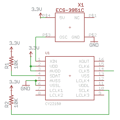
The crystal-controlled SoftRock receivers developed by Tony Parks (KB9YIG) have played a significant role in introducing many individuals to Software Defined Radio (SDR). For those who prefer not to be limited to a single frequency, the SoftRock Ensemble receivers...
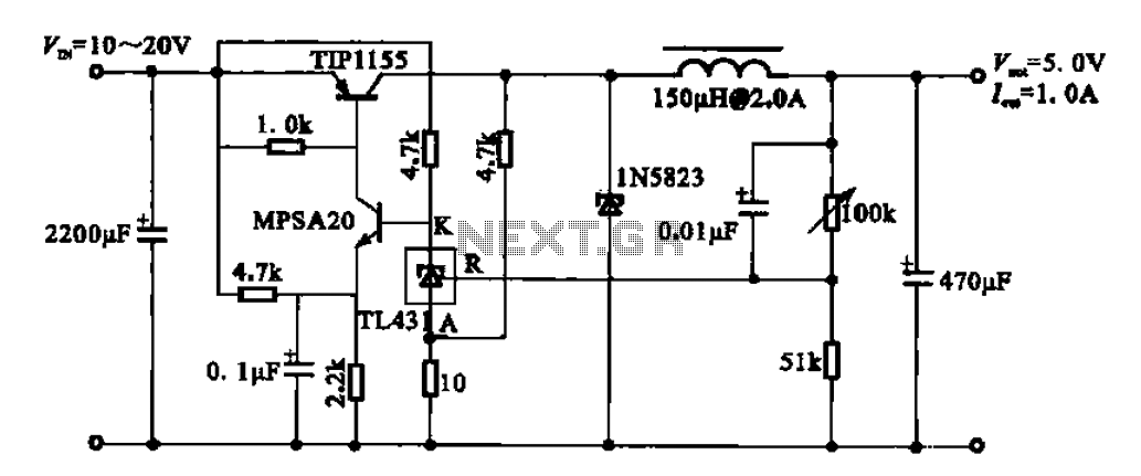
The 5V regulator circuit is designed to convert a DC input voltage ranging from 10V to 20V into a stable 5V output. This circuit features low power consumption and high efficiency. The 5V regulator circuit typically employs a linear voltage...
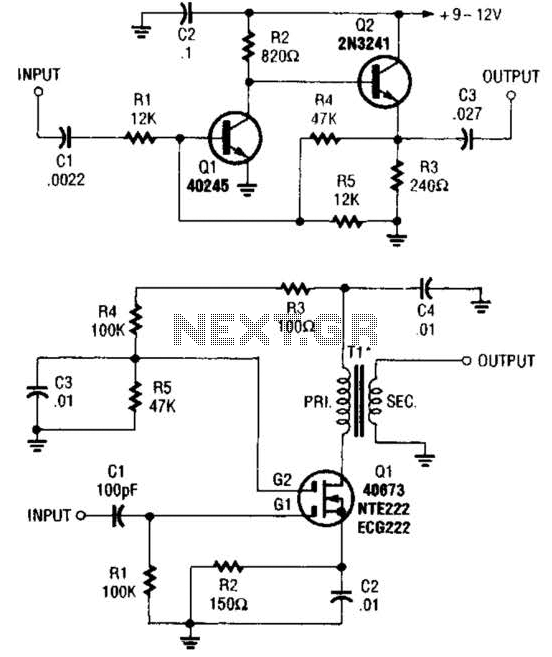
These two buffer/amplifiers have been effectively utilized with variable frequency oscillators (VFOs): one (depicted in A) is constructed using a pair of bipolar NPN transistors, while the other (illustrated in B) is designed around a dual-gate MOSFET. The first buffer/amplifier,...
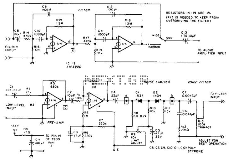
The noise limiter circuit features a preamplifier clipper and a switchable audio bandpass filter. Audio levels ranging from 5 to 50 mV are amplified in a preamplifier to several volts peak-to-peak, which are then sent to a clipper and...
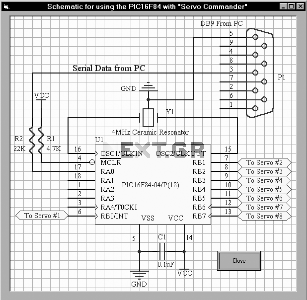
The first servo controller project at http://www.rentron.com/servo.htm had the com port fixed at com1. This new version will seek out the available com ports on your PC and then let you select the desired port and baud rates. It...
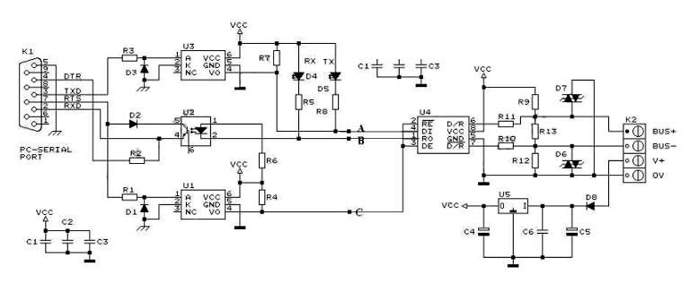
RS232 to RS485 Converter Circuit Schematic. RS232 to RS485 converters are primarily utilized in industrial and commercial settings. The RS232 to RS485 converter circuit is designed to facilitate communication between devices using different serial communication standards. RS232 is commonly found...