
Stepper motor getting very hot wrong driver or power supply
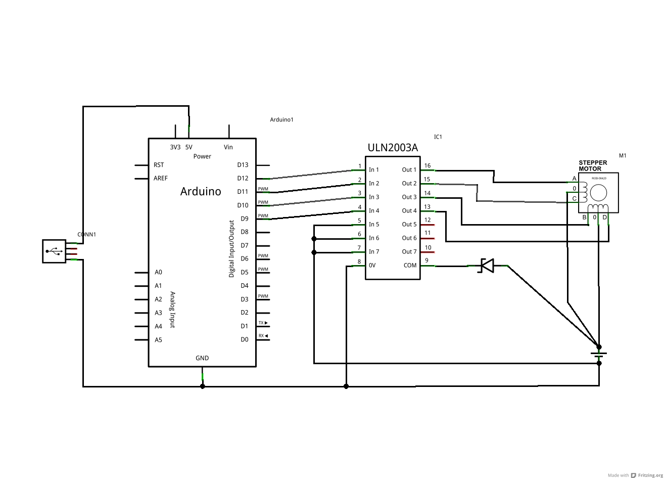
The schematic indicates that each center-tapped winding behaves like two magnetically coupled inductors or two halves of a transformer winding. When the center tap is connected to V+ and one end is grounded, the other end attempts to rise to 2 x V+, minus the diode drop. Each driven output connects via a diode to COM (anode to driver, cathode to COM), which creates a scenario where driving the supply results in an attempt to achieve 2 x supply voltage. This leads to undesirable heating effects, as observed.
For optimal performance, if a 2 x V+ rail is available, connecting COM to that rail is recommended. This setup would provide a nearly ideal solution. Alternatively, connecting COM to a capacitor will yield a 2 x V+ supply. A Zener diode should be connected from COM to ground (with Vzener > 2 x Vsupply) or from COM to V+ (with Vzener > V+), ensuring that the Zener cathode is connected to COM in both cases. This arrangement allows COM to rise to 2 x V+ without the Zener conducting.
The combination of a capacitor and resistor serves to provide a load for inductive spikes and to load the transformer formed by the two halves of the winding. The resistor connected to the capacitor helps mitigate unwanted loading. A resistor to ground can drain the capacitor, and its dimensions should be adjusted as necessary.
To verify these assertions, a practical test can be conducted by either disconnecting COM (with a slight risk of damaging the ULN2003) or connecting it to V+ with the Zener as described. Monitoring COM with an oscilloscope or connecting a capacitor rated for more than 2 x V+ from COM to ground while operating the stepper motor can help measure the capacitor voltage. Voltages approaching 2 x V+ should be observable. A circuit that nearly achieves this functionality is noted, though it is important to ensure that the Zener diode polarity is correct; reversing the polarity allows the Zener to function properly, enabling COM to rise to V+ + Vzener.The ULN2003A and Zener from the driver board inside the same device. It`s a 5 wires motor, but the one in the schematic is 6 wires. I suppose the only difference is that the 5 wire version has the two center taps joined together so that`s what you see in my schematic. The motor seems to run perfectly, however after a minute or so it becomes extremely hot. I don`t have anything to measure the actual temp but it is painful to put my fingers on it for more than half a second. given the circuit above, remove the zener and put a resitor and a 100uF 25V capacitor in series between COM and GND (COM -> R -> C -> GND): the motor runs well but still overheats What is the zener voltage The supply voltage needs to be lower than the zener voltage Also, what is the zener voltage Russell McMahon Oct 8 `11 at 16:01 Hot sounds wrong. What is the coil resistane when measured with an ohm meter (multimeter) center tap to any conmnected phase What is the supply current | If you have a 50 ohm coil then the power per phase max should be V2/R = 144/50 = 2.
9 Watt. Overall yu should not have more than the equivalent of 1 phase being driven cintinually. 3 Watt sis not vast heat wise. | IF you have the 8 Ohm version. :-). | 122/8 = 18W or I = V/R = 12//8 = 1. 5A = hotter than 3 Watts. | 8 ohm version is made to be pulse driven (or with series R). Russell McMahon Oct 11 `11 at 16:24 As you can see from your drawing (even though it tends not to be intuitive at first glance) - each centre tapped winding is like two magnetically coupled inductors or two halves of a transformer winding. When you connect the centre tap to V+ and ground one end the other end rises to 2 x V+ - or tries to.
BUT each driven output is connected via a diode to com (anode to driver, cathode to com). When you ground one end of the winding and the other end is connected to V+ via a diode you are trying to drive the supply with 2 x supply (less a diode drop). Something has to give. As you have discovered. In the unlikely event that you have a 2 x V+ rail, connect com to that. That would be a near perfect solution. If you connect com to a capacitor you will get a 2 x V+ supply :-). Connect a zener from com to ground (Vzener > 2 x Vsupply) or com to V+ (Vzener > V+). Zener cathode to com in each case so com can rise to 2 x V+ without zener conducting. The above schemes with capacitor and resistor provide a load for inductive spikes. They also load the transformer formed by the two halves so the resistor to the capacitor is to reduce the unwanted loading.
The resistor to ground drains the cap. Dimension as required. The easy practical test of my assertion is to either disconnect com (slight risk of ULN2003 dying) or connect to V+ with a zener as above, the monitor com with an oscilloscope. Or connect a capacitor with voltage rating > 2 x V+ from com to ground, operate stepper and measure capacitor voltage.
Voltages of ~=2 x V+ should appear. Here is one circuit which almost gets it right - except he has the zener diode polarity reversed. As shown the zener acts like a low grade diode with the same polarity as the ULN200x internal diodes. Reverse it and it lets com rise to V+ + Vzener. 🔗 External reference
Related Circuits
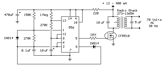
The interval between rings can be adjusted by changing the value of the 1 Meg resistor. A 70 volt, 30 Hz ringing voltage is generated from the 120 volt side of a small 12.6 VAC power transformer (Radio Shack...
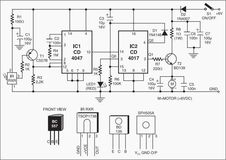
This add-on circuit enables remote switching on/off of battery-operated toy cars using a TV/video remote control handset operating at 3040 kHz. The described circuit utilizes a remote control system to facilitate the wireless operation of battery-powered toy cars. The primary...
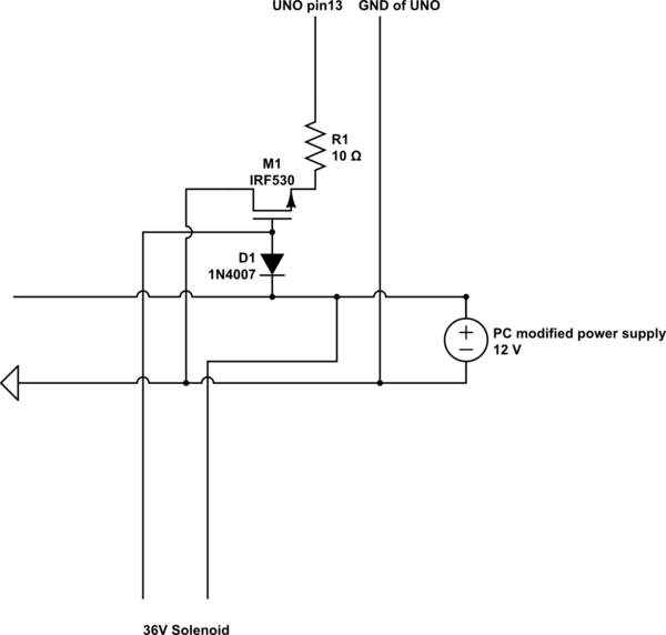
A 9 V DC battery initially powered the solenoid valve effectively. However, the solenoid did not generate sufficient force due to inadequate DC power. A modification was made to use a computer power supply as the power source. Providing...
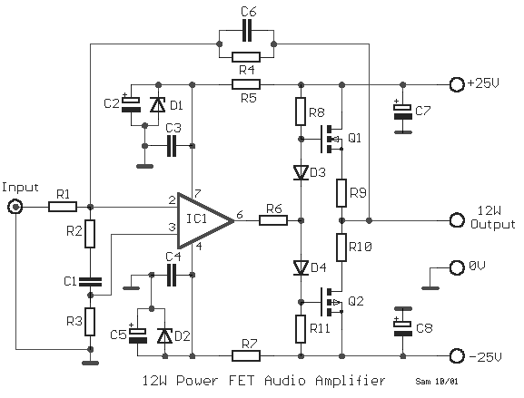
A compact power amplifier that delivers high-quality sound. It incorporates a NE5534 operational amplifier, known for its excellent performance, capable of handling low loads, providing high speed, and exhibiting low distortion. Additionally, it features two V-MOSFET transistors at the...

Diodes can be utilized instead of pull-up resistors, while isolating the DC load from the trigger circuit through junction drops and a 10nF capacitor. Excessive power from the solar cell may cause the motor to operate too frequently or...
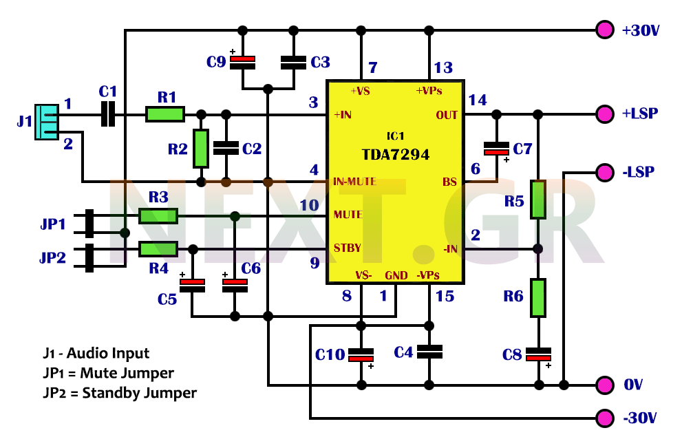
The integrated TDA7294 from SGS Thomson is a high-frequency acoustic power amplifier that boasts true high-precision specifications, making it suitable for various applications. Its standout feature is the significantly higher output power compared to typical amplifiers with similar distortion...