
Solar Powered Motor

The circuit leverages diodes to replace traditional pull-up resistors, which enhances efficiency by reducing power consumption. The isolation of the DC load from the trigger circuit is crucial for preventing feedback that could lead to erratic motor operation. This is achieved through the use of junction drops, which help manage voltage levels, and a 10nF capacitor that acts as a filter to smooth out any fluctuations in the signal.
The concern regarding excessive power from the solar cell is valid, as it can lead to unintended motor activation. To address this, a 100K ohm resistor is strategically placed in series with the solar cell. This resistor acts as a current limiter, ensuring that the voltage and current supplied to the motor remain within acceptable levels, thus preventing continuous operation or overheating.
In summary, the combination of diodes, a capacitor, and a series resistor creates a robust circuit design that effectively manages power levels, enhances performance, and ensures reliable operation of the motor under varying conditions. This design approach is particularly beneficial in solar-powered applications where fluctuating power levels can pose challenges.By using diodes in place of pull up resistors, and by isolating the DC load from the trigger circuit via junction drops and the 10nF capacitor. If there is too much power comming from the solar cell then the motor might run too often or even continuously.
You can avoid this by putting a 100K ohm resistor in serieswith the solar cell. 🔗 External reference
Related Circuits
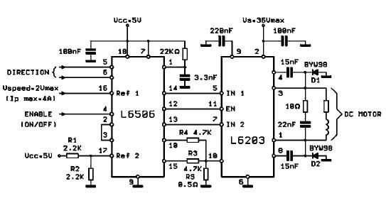
The L620x is a monolithic full bridge switching motor driver implemented using the new Multipower-BCD technology. This technology enables the integration of multiple isolated DMOS power transistors along with mixed CMOS/bipolar control circuits. The L620x series includes various versions:...
The following circuit illustrates the AC Motor Speed Controller Kit - K2636 Circuit Diagram. Features include standard dimmer functionality, utilizing carbon components. The AC Motor Speed Controller Kit - K2636 is designed to regulate the speed of AC motors, making...
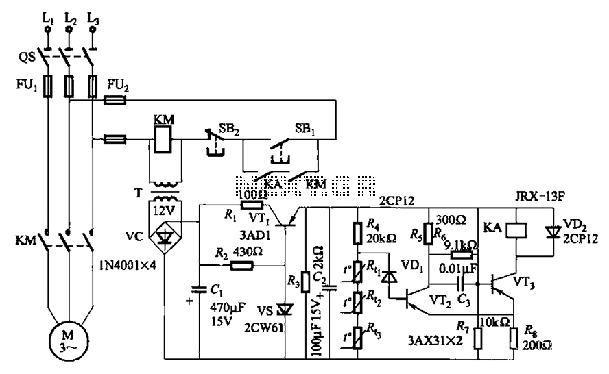
A P-type transistor (VT2, VT3) and other components form a common emitter-coupled trigger, functioning as a Schmitt trigger device. This setup serves as a switching circuit to detect changes in the resistance of a PTC thermistor, thereby controlling the...
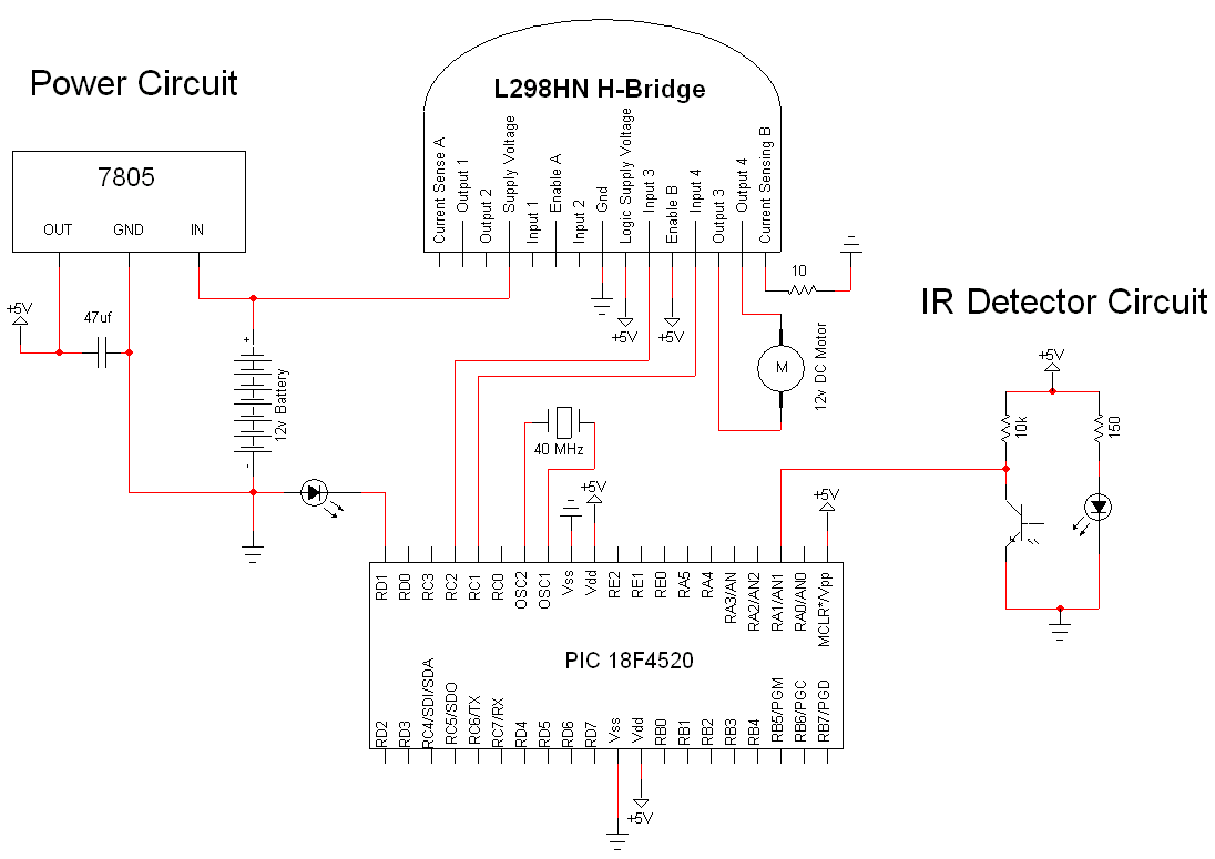
The simple motor optical encoder circuit is not particularly difficult; however, it requires careful verification to ensure all connections are correct before initial operation. The primary components utilized in the circuit include the 7805 voltage regulator, the PIC18F4520 microcontroller,...
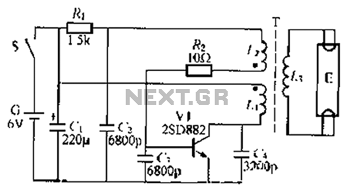
The circuit described is a battery-powered fluorescent lamp system designed for temporary emergency lighting during power outages. It utilizes a transistor (V7) and a boosting transformer (T) along with an inductive feedback oscillator to generate a high-voltage output. When...
An unconventional, scalable high-efficiency 12V solar power system and battery charge controller with low voltage cutout to protect the battery, ideal for systems of 50W or less. This circuit was designed for small to medium lead-acid systems and features...