
stereo balance indicator
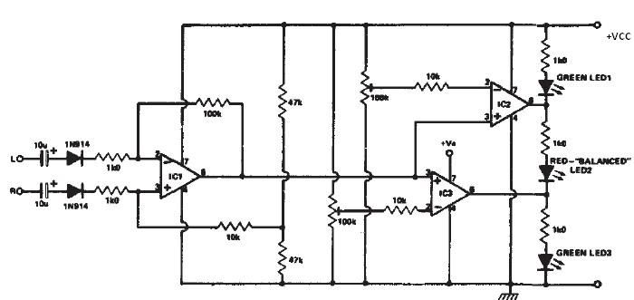
The stereo balance indicator circuit is a practical application for audio systems, enabling users to visually assess the balance between left and right audio channels. The circuit employs a differential amplifier configuration using an operational amplifier (IC1) to process the audio signals from both channels. The differential amplifier effectively amplifies the difference between the two input signals, allowing for precise detection of any imbalance.
The outputs of the differential amplifier (IC1) are routed to the non-inverting inputs of two additional operational amplifiers (IC2 and IC3). These amplifiers serve as comparators, determining the status of the audio balance. When the output from IC1 approaches the positive supply voltage, it indicates that the right channel is significantly stronger than the left, triggering IC2 and IC3 to output high signals. This condition activates LED3, providing a clear visual cue to the user.
Conversely, if the audio balance shifts toward the left channel, the outputs from IC2 and IC3 will drop to low levels, resulting in the illumination of LED1. This visual indication alerts the user to the dominance of the left channel. In a perfectly balanced scenario, where both audio channels are equal in amplitude, IC2 and IC3 will output a low signal for one and a high signal for the other, activating LED2. This setup allows for an intuitive understanding of the audio balance, essential for optimizing sound quality in various listening environments.
The circuit's simplicity and reliance on commonly available components make it an accessible project for audio enthusiasts and engineers alike. By implementing this stereo balance indicator in an audio system, users can ensure a more enjoyable listening experience through effective sound balance management.This stereo balance indicator circuit diagram is designed using few common external components. The schematic circuit is very simple to build and will provide an visual indication with LEDs for left, right and center balance. Outputs from each channel are fed to the two inputs of IC1 connected as a differential amplifier. Output of the IC1 is c onnected to the noninverting inputs of the IC2 and IC3. If the outputs of the IC1 approaches the supply rail, the outputs of the IC2 and IC3 will go high illuminating the LED 3, this will show that the right channel is dominating. If the sound is balanced to the left channel, the Ic2 and IC3 will go low and the LED1 will light. If both channels are equal in amplitude the outputs of the IC2 and IC3 would be low and high respectively, lighting up LED2.
🔗 External reference
Related Circuits
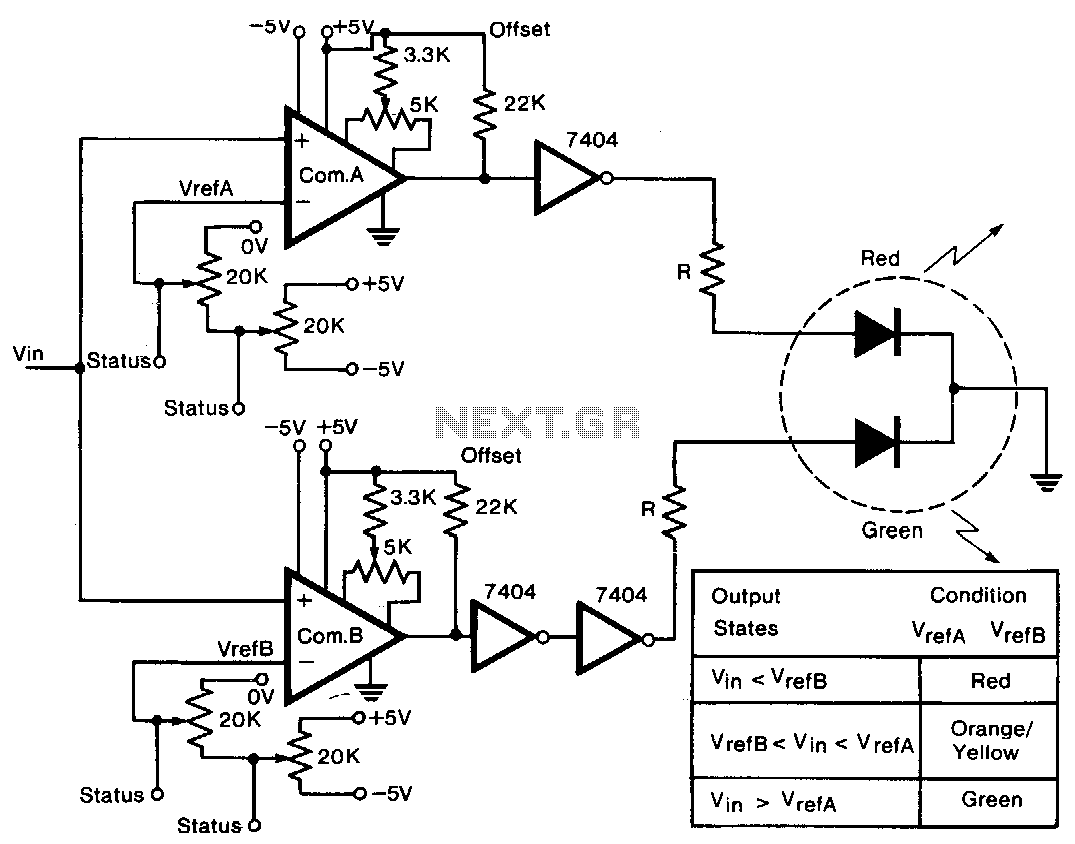
A tricolor LED serves as the visual indicator for voltage levels. The voltage to be measured is connected to two comparators in parallel. The first 20-KΩ trimmer sets a reference voltage between ±5 V, establishing the full-scale reference value....
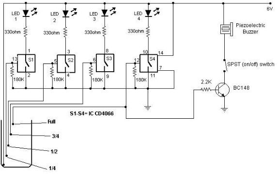
A simple and cost-effective water level indicator circuit can be designed using this schematic. This water level indicator utilizes a CMOS IC CD4066 to indicate the amount of water present in an overhead tank and to provide an alarm...
The article presents a circuit that can be used for indicating the riding speed of a bicycle. The bicycle speedometer circuit explained here utilizes standard components such as transistors and LEDs to effectively display a clear 10-step, accurately calibrated...
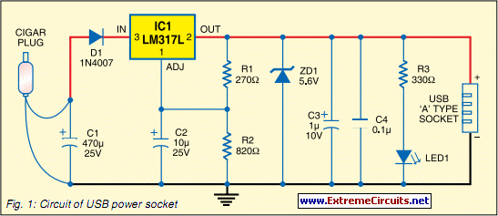
Today, nearly all computers are equipped with logic blocks designed to implement a USB port. In practice, a USB port can deliver over 100 mA of continuous current at 5V to the peripherals connected to the bus. This capability...
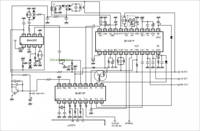
The BA3822LS, BA3822FS, BA3823LS, and BA3824LS are monolithic, five-point stereo graphic equalizer integrated circuits (ICs). Each IC features two channels, with five center frequencies for each channel that can be independently set using external capacitors. These ICs support a...
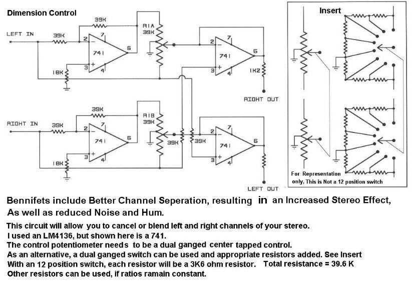
The circuit includes better channel separation, resulting in an increased stereo effect, as well as reduced noise and hum. This schematic will allow you to cancel or blend left and right channels of your stereo. Uses the LM4136 but...
Warning: include(partials/cookie-banner.php): Failed to open stream: Permission denied in /var/www/html/nextgr/view-circuit.php on line 713
Warning: include(): Failed opening 'partials/cookie-banner.php' for inclusion (include_path='.:/usr/share/php') in /var/www/html/nextgr/view-circuit.php on line 713