
Stereo balance tester
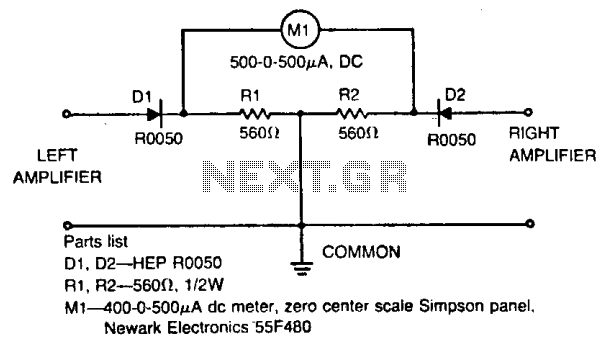
The described circuit is a stereo balance meter that provides visual feedback on the audio signal levels from a stereo amplifier setup. The zero-center meter is crucial for indicating whether the audio signals from the left and right channels are balanced. When both channels are equally powered, the meter should ideally read zero, which signifies that the audio output is in phase and that both speakers are matched in terms of output level.
The choice of using five percent tolerance resistors ensures that the circuit maintains a reasonable degree of accuracy in its readings, minimizing errors that could arise from component variations. Matched diodes are essential in this circuit to ensure that the signal processing remains consistent, as any discrepancies in diode characteristics could lead to incorrect readings on the meter.
In practical applications, if the meter displays a reading away from zero, it indicates a potential issue with the audio setup. This could be due to mismatched speaker impedances or incorrect wiring configurations, which can cause phase issues. To troubleshoot, it is recommended to check the connections to ensure that the meter leads are properly connected to the amplifier's hot terminals. The common leads should be securely grounded to provide a stable reference point for the measurements.
This balance meter circuit can be integrated into various audio systems to enhance user experience by allowing for easy adjustments to achieve optimal sound quality. Proper calibration and setup are vital for ensuring that the meter functions accurately, thereby facilitating the correct adjustment of audio levels for an immersive listening experience.The meter will show volume and tone control balance between left and right stereo amplifiers. For maximum convenience the meter is a zero-center type. Resistors are five percent or better and the diodes a matched pair. Optimum stereo level and phase balance occurs for matched speakers when the meter indicates zero. If the meter indicates either side of zero, the levels are not matched or the wires are incorrectly phased. Check phasing by making certain the meter leads are connected to the amplifier hot terminals and the common leads go to ground.
🔗 External reference
Related Circuits
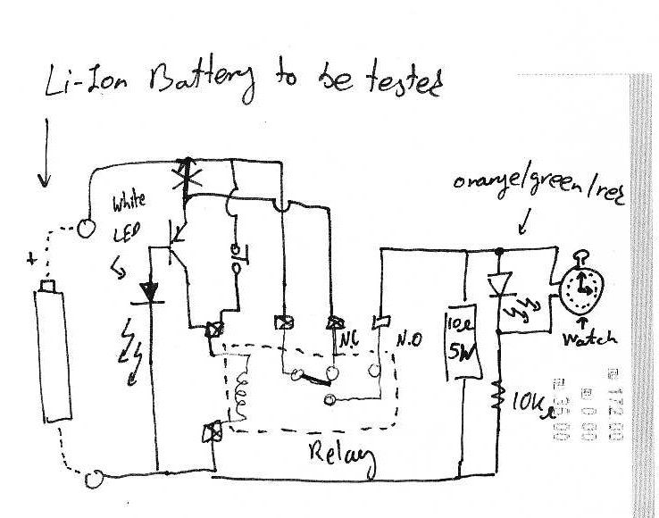
It is assumed that individuals interested in constructing this circuit can interpret the schematics provided below. Basic principles: Note that lithium-ion batteries should not be discharged below 3V. The circuit design focuses on the safe operation of lithium-ion batteries, particularly...
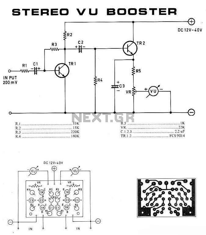
This is a stereo VU booster circuit diagram based on the transistor FCS9014, which is commonly used for pre-amplifier and regulator circuits. This circuit should be connected to the audio channel before the amplifier module. If tone control or...
Testing whether a transistor is shorted or open is typically performed using an ohmmeter. The test involves checking if current can flow between the base and emitter or the collector. To effectively test a bipolar junction transistor (BJT) for shorted...
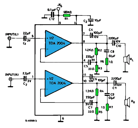
The TDA2004 integrated circuit (IC) is a popular choice among audio electronics enthusiasts due to its affordability and availability. This IC is often utilized in audio amplifier designs because it features two outputs and inputs, making it easy to...
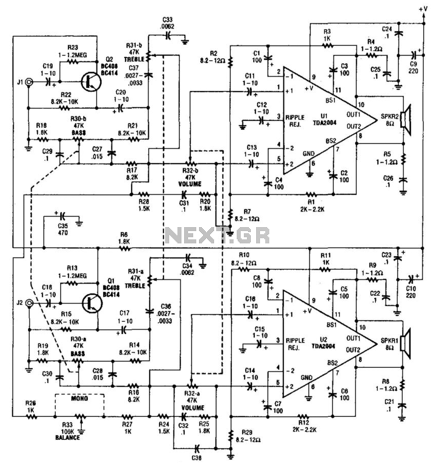
This amplifier delivers 20 W per channel with an input sensitivity of approximately 300 mV into a 47 kΩ load. It utilizes a bridged output configuration, allowing the speakers to be operated with both wires above ground. A +12...
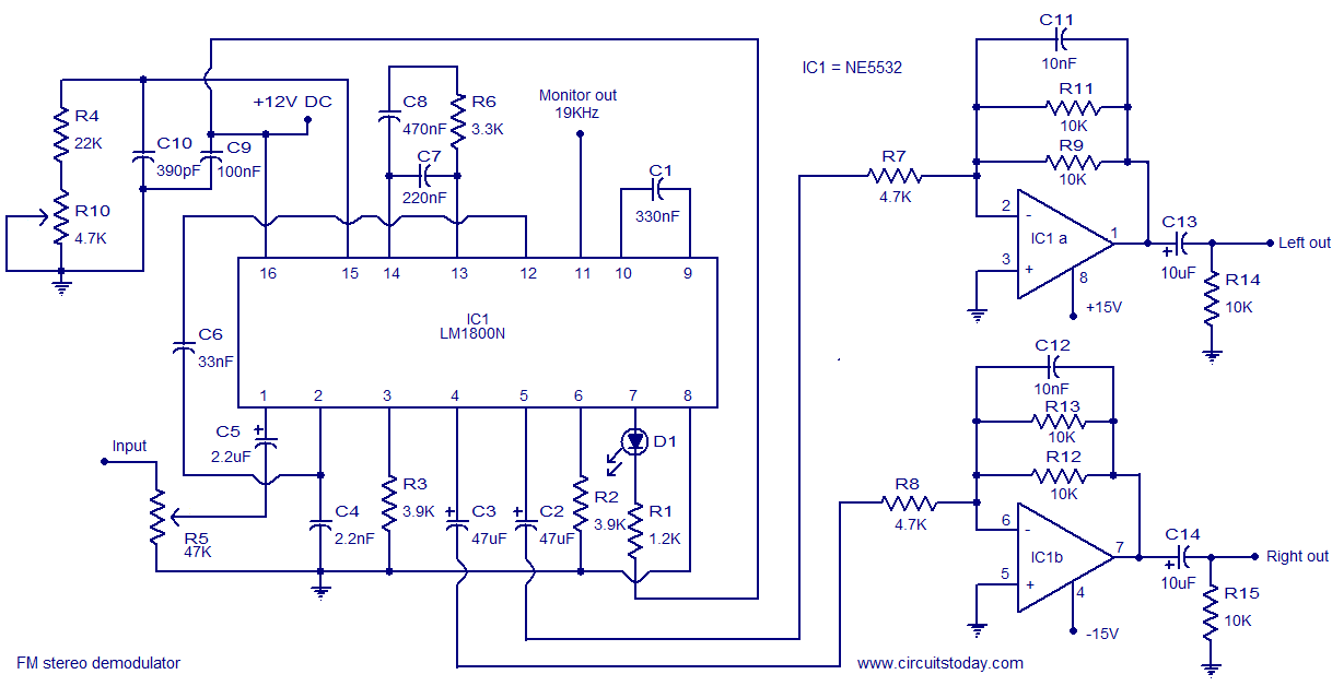
The following circuit illustrates the LM1800 IC Integrated FM Stereo Demodulator Circuit. Features include excellent sound quality and high-quality FM stereo. The LM1800 Integrated Circuit (IC) serves as a highly effective FM stereo demodulator, designed to deliver superior audio performance...