
LM1800 IC Integrated FM Stereo Demodulator Circuit

The LM1800 Integrated Circuit (IC) serves as a highly effective FM stereo demodulator, designed to deliver superior audio performance in various applications. This circuit is particularly well-suited for radio receivers that require high fidelity stereo sound. The LM1800 is capable of demodulating FM signals and extracting stereo audio from the received signal, ensuring that the output maintains clarity and richness.
The circuit typically consists of several key components: the LM1800 IC itself, which handles the demodulation process; passive components such as resistors and capacitors that set the operating conditions; and additional circuitry for audio output and filtering. The IC integrates a stereo decoder, which separates the left and right audio channels, allowing for true stereo sound reproduction.
Power supply considerations are crucial for the LM1800 circuit, as it requires a stable voltage source to function optimally. The typical operating voltage range for the LM1800 is between 9V and 15V. Proper bypass capacitors should be included near the power pins to minimize noise and ensure stable operation.
Input signals are received via an antenna, which is connected to the RF input of the LM1800. The circuit may include additional stages for RF amplification and filtering to enhance the quality of the incoming signal before it reaches the demodulator. The output stage of the circuit typically connects to an audio amplifier or directly to speakers, depending on the application.
Overall, the LM1800 FM stereo demodulator circuit is a robust solution for high-quality audio applications, providing excellent sound reproduction and ease of integration into various electronic systems.The following circuit shows about LM1800 IC Integrated FM Stereo Demodulator Circuit. Features:excellent sound quality, high quality FM stereo, .. 🔗 External reference
Related Circuits
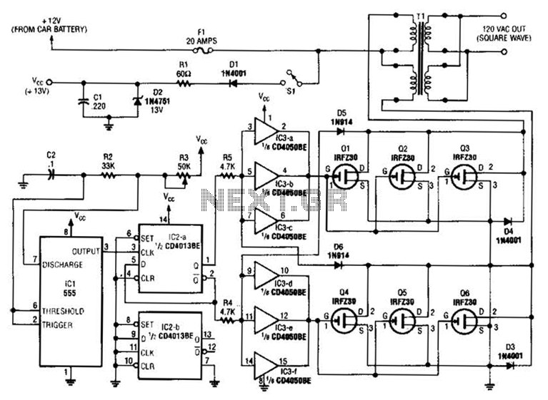
A 555 timer (IC1) generates a 120-Hz signal that is fed to a CD4013BE flip-flop (IC1-a), which divides the input frequency by two to generate a 60-Hz clocking frequency for the FET array (Q1 through Q6). Transformer T1 is...
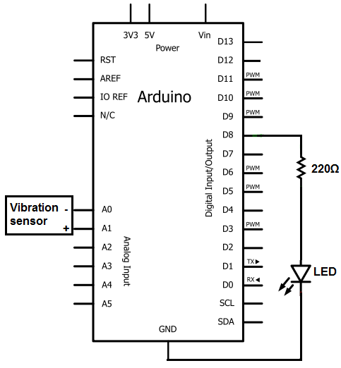
The sensors consist of a thin strip of piezoelectric material with a rivet at one end acting as a weight. When vibration occurs, the weight moves, stressing the piezo material, which generates a spike in voltage that can reach...
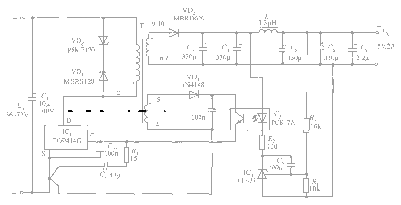
The circuit diagram includes an input filter capacitor C1 and a primary clamp composed of VDz and VD1. The resistor R1 is connected to the control terminal. C2 serves as a bypass capacitor. The TOP414GC-S is connected in parallel...
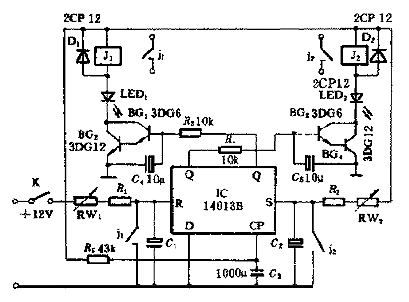
The timing control circuit is a sequential circuit that allows for sequential timed control of two switches. The control time can be adjusted from a few seconds to several tens of seconds. If mechanical control is applied for reciprocating...
The circuits examined thus far rely on linear feedback for their operation. The magnitude of the signal returned to the negative input is always strictly proportional to the output voltage. Consequently, within the limits defined by the operational amplifier...
A 1000 Watts audio power amplifier circuit designed for outdoor use. A circuit diagram is needed urgently to facilitate the construction of this high-power amplifier, which is a personal passion project. The design of a 1000 Watts audio power amplifier...