
Stereo VU Booster
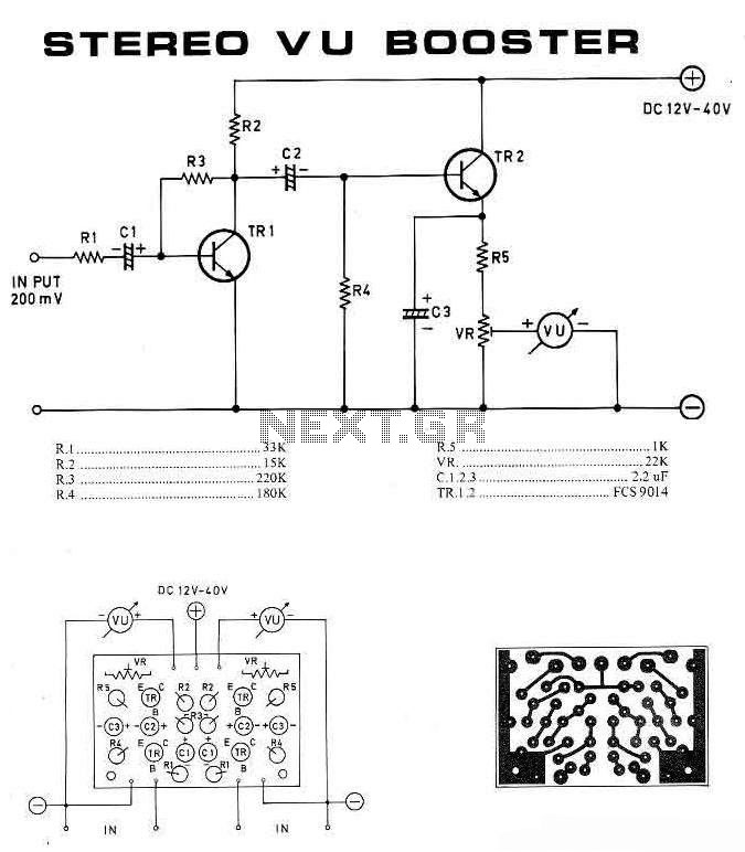
The stereo VU booster circuit featuring the FCS9014 transistor serves as an essential component in audio processing systems, particularly in enhancing audio signals prior to amplification. The FCS9014 is a versatile transistor known for its low noise characteristics and high gain, making it suitable for pre-amplification tasks.
In the schematic, the circuit typically includes input and output stages, with the input stage receiving the audio signal from the source. The FCS9014 is configured in a common-emitter arrangement, which allows for voltage amplification while maintaining a low output impedance. This configuration is beneficial for driving subsequent stages, such as tone control or equalizers, before the final amplification.
The circuit may also incorporate resistors and capacitors to set the biasing conditions for the FCS9014, ensuring optimal performance. For instance, a resistor connected to the base of the transistor can help establish the correct operating point, while coupling capacitors may be used to block DC components, allowing only the AC audio signal to pass through.
Additionally, the circuit may feature LED indicators that visually represent the audio signal levels, providing a visual cue for monitoring purposes. These LEDs can be connected in parallel with the output, allowing them to illuminate in response to the audio signal's amplitude.
Overall, the stereo VU booster circuit is a critical element in audio systems, enhancing the quality and clarity of sound before it reaches the amplifier, thus improving the overall listening experience. Proper implementation of this circuit ensures that audio signals are amplified effectively without introducing significant distortion or noise.This is a stereo VU booster circuit diagram based on transistor FCS9014 which usually used for pre-amp and regulator circuit. This circuit should be connected to audio channel before amplifier module. If you are using tone control or equali.. 🔗 External reference
Related Circuits
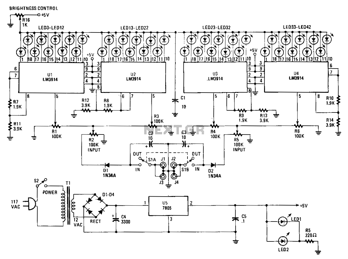
The Stereo Power Meter consists of two identical circuits and a power supply. Each circuit features two LM3914 display chips, which include 10 voltage comparators, a 10-step voltage divider, a reference voltage source, and a mode-select circuit that allows...
Most cards of sound in computer are deprived stereo input for microphone; on the contrary, they have stereo input for high level (Line). The circuit uses the input Line of the sound card in order to connect two mono...
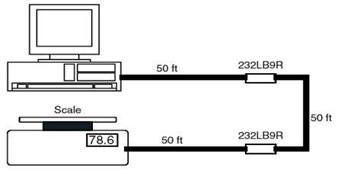
This is the schematic diagram of a 9-Pin RS232 Line Booster Signal Direction. The device functions as a 9-pin RS-232 repeater, re-transmitting all 8 signals while also maintaining the ground line. The 9-Pin RS232 Line Booster is designed to extend...
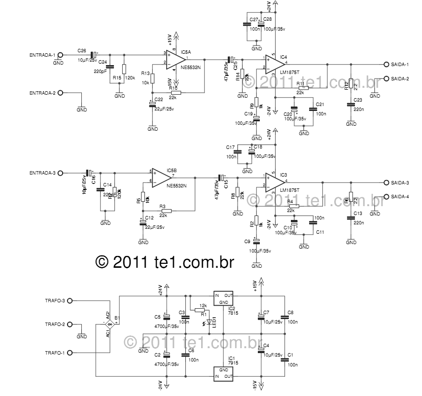
The LM1875 delivers 20 watts into a 4 or 8-ohm load on ±25V supplies. Using an 8-ohm load and ±30V supplies, over 30 watts of power may be delivered. The amplifier is designed to operate with a minimum of...
The circuit is straightforward yet capable of outstanding performance. It has been specifically designed as an amplifier for the digital sound card in a computer. Audio input can be sourced from any two-channel line-level device such as a television,...
This is a Turbo Bass circuit. Using this circuit, low-frequency sound signals (bass) can be amplified. This circuit is an active circuit. The first op-amp... The Turbo Bass circuit is designed to enhance low-frequency audio signals, specifically targeting the bass...