
Stereo sound balancer
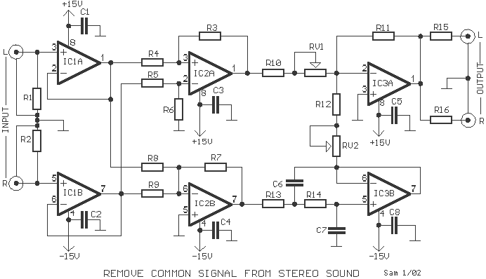
The described circuit serves the purpose of removing or reducing the vocal track from a stereo audio signal while preserving the bass frequencies. The fundamental principle of this circuit relies on the subtraction of the left and right audio channels, which typically contain the vocal information at equal levels. By utilizing the configuration of signals [L+R] and [L-R], the circuit effectively extracts a mono signal that minimizes vocal presence, while keeping the bass intact.
The circuit employs a series of operational amplifiers, specifically the TL072 ICs, which are known for their low noise and high performance in audio applications. The first two operational amplifiers, IC1 and IC2, are configured to handle the input signals from the left and right channels. Resistors R1 and R2, both rated at 100 kΩ, ensure appropriate gain levels for the operational amplifiers.
The configuration of resistors R3, R4, R5, and R6, each at 10 kΩ, is critical for creating the differential signal necessary for vocal cancellation. The output from IC1 and IC2 is fed into the third operational amplifier, IC3, which acts as an adder. This stage combines the low-frequency components from both channels while eliminating the vocal frequencies that are common to both channels.
The balance between the two input signals is adjusted using variable resistors RV1 and RV2, both logarithmic taper potentiometers, with RV1 set at 100 kΩ and RV2 at 250 kΩ. This allows for fine-tuning of the output signal to achieve the desired vocal reduction without significantly altering the bass response.
To maintain signal integrity, the circuit avoids the use of capacitors in the signal path, as they can introduce phase shifts that may adversely affect audio quality. Instead, the design utilizes high-quality components, including 1% tolerance metal film resistors, to ensure accuracy and minimize noise.
The capacitors used in the circuit, such as C1 to C5 (100 nF ceramic) and C6, C7 (180 nF and 120 nF MKT respectively), are employed for coupling and decoupling purposes, ensuring stable operation without affecting the audio signal's phase characteristics.
In conclusion, this circuit design effectively addresses the challenge of vocal removal in stereo audio signals while preserving the essential low-frequency content, making it a valuable tool for audio engineers and enthusiasts seeking to enhance their audio mixing capabilities.It many times happens, we want erase or decrease in a musical song, the voice of singer or some other sound that usually is written in same level and in the two channels. If we remove between them two signals of channels, we can take in the output a mono signal without the voice.
Here exist a problem. The sound of bass instrument is also this written in two channels. With this circuit, the bass they can be not removed, if it is added in the signal [ L+R ], the signal [ L-R ]. The signal of low frequencies and the signal of difference, are applied in adder IC3?. The balance between, regulated from the RV1-2. In the circuit do not exist capacitors in the line of signal, because add undesirable drift of phase in the signal of input.
Attention should be given in the quality of materials of circuit. The resistors should anyhow be is precision 1% metal film. Elektor 8/89 Part List R1-2=100Kohm R13-14=5.6Kohm IC1-2-3=TL072 R3-4-5-6-10=10Kohm R15-16=100ohm RV1=100Kohm Log. R7-8-9=6.8Kohm C1-2-3-4-5-8=100nF ceramic RV2=250Kohm Log. R11=27Kohm C6=180nF 100V MKT R12=47Kohm C7=120nF 100V MKT All the Resistors is 1/4W 1% metal film 🔗 External reference
Related Circuits
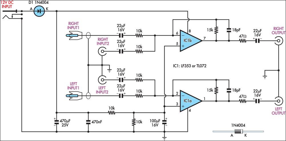
This circuit combines two separate line-level stereo (left and right) signals into a single stereo output, eliminating the need to switch between two sets of input signals. In this application, it is utilized to connect stereo audio from a...
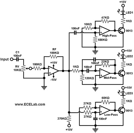
Figure 1 illustrates a simple circuit designed for converting an audio signal (such as one from the output terminals of a CD player). The circuit primarily consists of a buffer/amplifier stage and three filtering circuits: a high-pass filter, a...
This is a less polished version of Handmade Electronic Music, featuring nearly identical content and available for free. Notably, refer to Chapters 18 and 20. The layout consists of conductive metal strips beneath the perforations of the breadboard. Typically,...
Construct an accurate LC Meter (Capacitance Inductance Meter) to facilitate the creation of coils and inductors. This LC Meter is capable of measuring very small inductances, making it an ideal tool for various RF coil and inductor applications. The...
This circuit generates a two-tone effect similar to the sound of a cuckoo. It can be utilized for doorbells or other applications due to its integrated audio amplifier and loudspeaker. The circuit is designed to produce a distinctive two-tone sound,...
The LM4844 is an integrated audio subsystem designed for stereo cell phone applications. Operating on a 3.3V supply, it combines a stereo speaker amplifier delivering 495mW per channel into an 8Ω load and a stereo OCL headphone amplifier delivering...