
Dual Input-Combining Stereo Line Amplifier
This circuit serves as an effective solution for integrating audio signals from multiple sources into a single output without the hassle of manual switching. The design incorporates a combining amplifier that merges the audio signals from the TV and the DVD player seamlessly. The choice of using component video for the DVD player ensures that the video quality is maintained at a high standard, while the audio output remains flexible for amplification.
The use of 15 kΩ resistors for gain control allows for customization based on the specific requirements of the audio system in use, enabling adjustments to the output level as necessary. The input impedance of 10 kΩ is suitable for most line-level audio sources, ensuring compatibility with a wide range of equipment.
The isolation provided by the 47 Ω series resistors is crucial in preventing any unwanted interaction between the outputs and the input capacitance of the connected amplifiers or cables, thereby preserving audio quality. The circuit's power requirements are modest, allowing it to be powered by a common 12V DC plugpack, making it convenient for various applications.
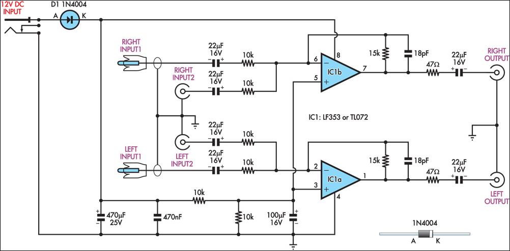
Overall, this circuit design not only simplifies the audio management between multiple devices but also enhances the overall audio experience by ensuring that high-quality signals are delivered to the external amplifier without conflicts or quality loss.This circuit takes two separate line-level stereo (L & R) signals and combines them into one stereo (L & R) output, thus avoiding the need to switch between two pairs of input signals. In the author`s application, it is used to feed the stereo audio from a TV receiver and a DVD player into an external amplifier.
The need for the circuit arose beca use of a design peculiarity in the TV receiver. The TV has four A/V inputs and one A/V output. AV1-AV3 accept composite or S-video plus stereo audio inputs and these feed into the TV`s A/V output. AV4 accepts Component video (Y/Pb/Pr) plus stereo audio but unlike AV1-AV3, its audio (and video) signals are not fed to the TV A/V output.
The Y/Pb/Pr input was chosen for use with the DVD player because of its superior video quality, while the audio was to be fed to an external amplifier for improved reproduction. However, manual switching was inconvenient, hence the genesis of this design. In use, the DVD player audio is fed in parallel to TV AV4 and to one input pair of the combining amplifier, while the TV audio output feeds the other input pair.
The amplifier output goes to the external audio amplifier. There is no conflict between the two audio inputs because when AV4 (DVD player) is selected, there is no TV audio output. In all other modes, the DVD player is off. As shown, the circuit has a voltage gain of 1. 5 times (3. 5dB) but this can be altered as required by changing the two 15kW resistors. Input impedance is 10kW and the outputs are isolated from cable and amplifier input capacitance with 47W series resistors.
The circuit can be powered from a regulated 12V DC plugpack. Be the first of your friends to get free diy electronics projects, circuits diagrams, hacks, mods, gadgets & gizmo automatically each time we publish. Your email address & privacy are safe with us ! 🔗 External reference
Related Circuits

This amplifier was designed to be self-contained in a small loudspeaker box. It can be fed by Walkman, Mini-Disc, iPod, CD players, computers, and similar devices fitted with line or headphone output. Of course, in most cases, you will...
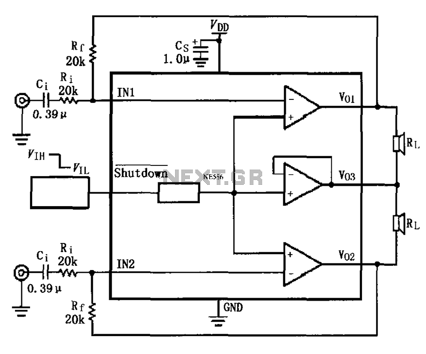
The LM4910 typical circuit is designed for a two-channel amplifier. The left and right channel audio signals are input to the LM4910 (in an MSOP/SO package) at pins 1 and 2. The output signals are delivered from pins 6,...
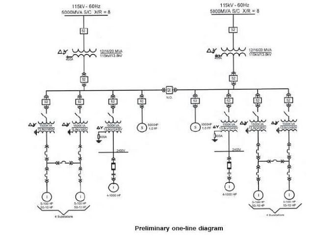
The single line diagram is a circuit diagram where a "one-line" representation illustrates the three phases of a three-phase power system. In addition to displaying the ratings and sizes of electrical equipment and circuit conductors, a well-drawn one-line diagram...
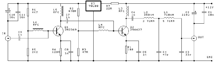
This project involves a 250mW RF power amplifier circuit. It is designed to amplify the output of approximately 7mW wideband FM transmitters to a final output level of about 250mW. The circuit utilizes a simple two-transistor VHF power amplifier...
With this simple project, you can have balanced lines too, simply adapting the unbalanced inputs and outputs of your hi-fi gear to become balanced, and then back to unbalanced at the other end. You can even be extra cunning,...
A simple preamplifier circuit is often required, utilizing a few components for ease of construction. This circuit employs an operational amplifier, specifically the Motorola TCA5550, which features a dual amplifier configuration. It provides outputs for adjusting volume, balance, treble,...