
Stereo Tone Control
This tone control circuit employs a single integrated circuit (IC), which simplifies the design and minimizes the footprint on a PCB (Printed Circuit Board). The circuit is versatile and can be implemented in various audio applications, including amplifiers, standalone modules, or integrated into musical instruments. The power supply requirements are straightforward, with a range of 9V to 15V, allowing for flexibility in power source selection. However, it is important to note that at the lower end of this range (9V), the bass response may be less pronounced.
The tone control features several user-adjustable parameters. The contour control, S1, modifies the overall tonal characteristics, allowing the user to tailor the sound profile. The volume control (P1) adjusts the output level, while the balance control (P2) enables the user to manage the levels between the left and right audio channels. For tonal adjustments, P3 and P4 are designated for bass and treble control, respectively, allowing for fine-tuning of the audio output.
Input and output connections are facilitated through connectors J1 to J4. J1 and J2 serve as the left and right inputs, respectively, while J3 and J4 provide the corresponding outputs. The circuit is designed to accommodate both line-level and microphone-level signals, making it suitable for a wide range of audio sources. In cases where a stronger input signal is anticipated, it is advisable to implement a voltage divider to ensure the input levels are within the acceptable range for optimal performance.
For integration into other circuits, it is possible to bypass the input and output connectors (J1-J4) if the tone control module is to be embedded directly into another system. This flexibility enhances the circuit's usability across different audio projects, making it a valuable component in audio engineering. Overall, this tone control circuit offers a compact, efficient solution for audio signal processing, with user-friendly features that cater to diverse audio needs.This simple tone control can be used in may audio applications. It can be added to amplifers, used as a stand alone control module, or even built into new and exciting instruments. It`s one IC construction makes it a very compact circuit, as only a few support components are required.
Plus, it does not use a dual power supply. This means that the circuit will run from VCC = 9V to 15V (although the bass will be a little weak at 9V). S1 is a contour control. Volume is controlled by P1. Balance is controlled by P2. P3 and P4 control bass and treble, respectivly. J1 is the left input, J2 is the right input. J3 is the left output, J4 is the right output. The circuit is designed to accept line level or mic level inputs. if you are going to be using a stronger signal, a voltage divider will be necessary to cut it down to proper levels. You can, of course, skip J1-J4 if you plan to integrate this circuit into another. 🔗 External reference
Related Circuits

Varies the speed and direction of a 5-amp reversible series AC motor according to a DC control signal. The polarity of the control signal determines the direction of rotation. A gain potentiometer adjusts the slope of the speed versus...
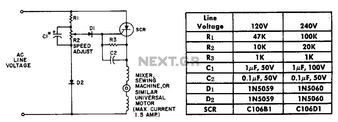
The resistor-capacitor network R1-R2-C1 generates a ramp-type reference voltage that is superimposed on an adjustable DC voltage controlled by the speed-setting potentiometer R2. This reference voltage, available at the wiper of R2, is compared against the residual counter electromotive...
This page features a circuit that has twenty open collector outputs that turn on one at a time in a continuous sequential manner. The circuit utilizes the 74LSxx family of TTL integrated logic devices. The circuits are designed to...
This circuit is designed to serve as a programmable LED display for various applications. It features an 8 x 32 LED dot matrix interfaced with a Xino (or Arduino). In addition to the display, the circuit includes two buttons...
Constantly changing light and sound analog controller circuit 02 The circuit described is an analog controller designed to modulate light and sound in a dynamic manner. It typically utilizes components such as operational amplifiers, resistors, capacitors, and transistors to achieve...
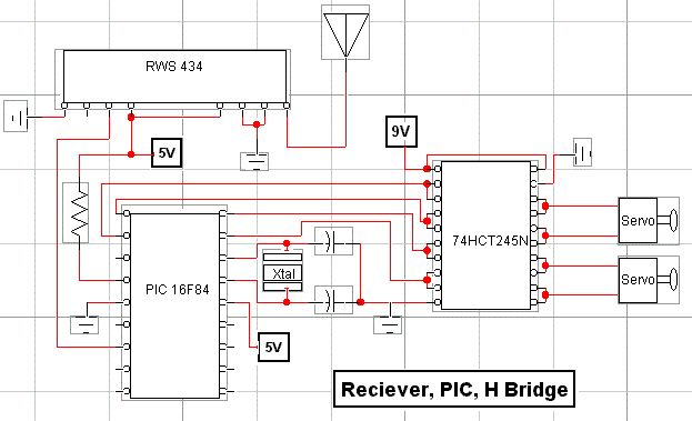
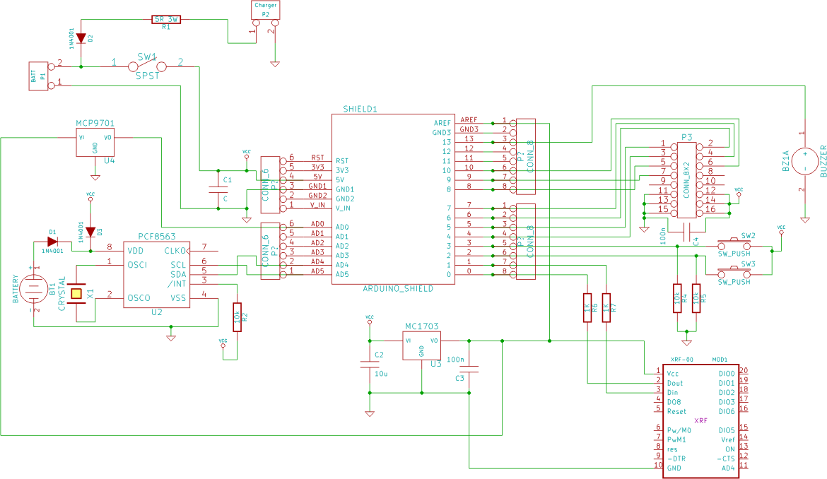
RF technology is an exciting field to incorporate into electronic designs. However, for beginners, constructing reliable RF transmitters and receivers can be challenging. RF (Radio Frequency) technology plays a crucial role in modern communication systems, enabling wireless data transmission over...