
TRIAC DIAC REVERSING SERVO CONTROL

The circuit described operates a 5-amp reversible series AC motor by utilizing a DC control signal to modulate both speed and direction. The key component in this system is the bidirectional static switch, which allows for the control of AC power to the motor based on the polarity of the incoming DC signal. When the control signal is positive, the motor will rotate in one direction, while a negative signal reverses the rotation.
To achieve variable speed control, a gain potentiometer is integrated into the circuit. This potentiometer alters the slope of the speed versus control voltage curve, providing fine-tuning of the motor’s response to the control signal. By adjusting the potentiometer, the user can set how quickly the motor responds to changes in the control voltage, allowing for smoother acceleration and deceleration.
The circuit may also include additional components such as diodes for protection against back EMF generated by the motor, as well as capacitors to filter noise from the control signals. Proper heat dissipation measures should be considered as well, especially when operating at higher currents, to ensure reliability and longevity of the components involved.
Overall, this system provides a versatile solution for applications requiring precise control of AC motor speed and direction, making it suitable for various industrial and automation tasks.Varies speed and direction of 5-amp reversible series ac motor in accordance with d-c control signal. Polarity of control signal determines direction of rotation. Gain potentiometer adjusts slope of speed versus control voltage curve. -M. P. Southworth, Bidirectional Static Switch Simplifies Ac Control, Control Engineering, March 1964, p 75-76.
🔗 External reference
Related Circuits
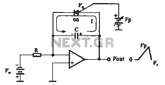
A sawtooth voltage-controlled oscillator operates by first generating a negative potential maximum at the output of the comparator. This output is then fed to the inverting input terminal through resistor R1, which is part of the relaxation oscillator. The...
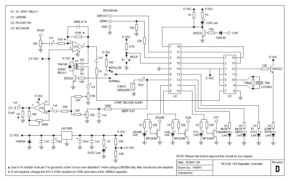
The project involves testing the capabilities of a PICAXE-18X chip operating at 4 MHz for a specific application. It includes designing the circuit, creating printed circuit board (PCB) artwork, etching the PCB, programming the PICAXE in BASIC, and connecting...
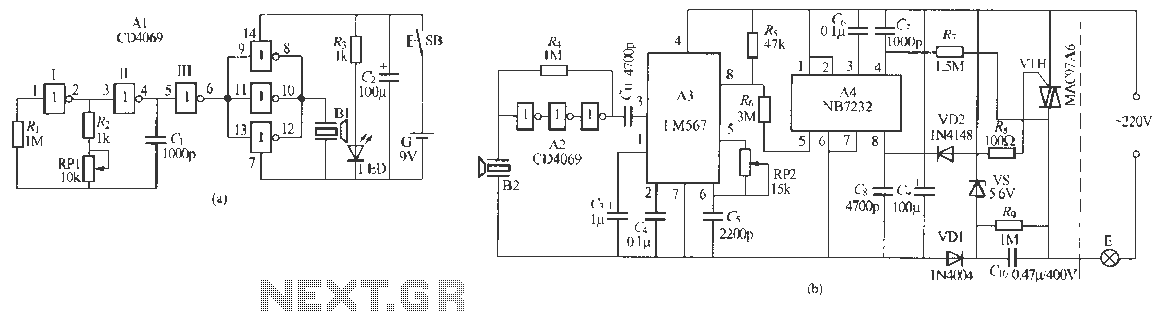
Remote control dimmer lights consist of two parts: an ultrasonic transmitter and an ultrasonic remote control dimmer receiver. The ultrasonic wave transmitter circuit is detailed in A 229 (a). It includes components such as R, R., RP1, and C,...
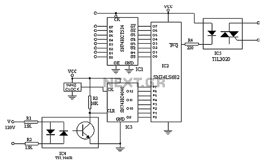
A simple digital circuit is presented that can be used to precisely control the AC power supply. This circuit does not include a digital-to-analog conversion component. In its application, effective control is established through a computer system that sends...
DC motors can be operated remotely using controls transmitted via an RF module. This circuit employs an RF module to manage DC motors through a motor driver integrated circuit (IC) L293D. Transmission is initiated by setting pin 14 (TE,...

This article continues from the previous one regarding the single character LCD display using an AVR microcontroller. The prior article demonstrated how to display a single letter on an LCD. This article advances the learning process by explaining how...