
Using a real time clock with a microcontroller
The circuit is designed to operate as an interactive LED display, leveraging an 8 x 32 LED dot matrix to present information visually. The microcontroller, either a Xino or Arduino, serves as the primary control unit, interfacing with various components including user input buttons, a temperature sensor, a buzzer for auditory feedback, and a wireless communication module for connectivity.
The real-time clock (RTC) is a critical component for maintaining accurate timekeeping. The PCF8583 RTC chip is chosen for its affordability and functionality, utilizing the I2C communication protocol for easy integration with the microcontroller. The chip's external oscillator, a 32.768 kHz watch crystal, provides the timing reference necessary for precision. The inclusion of 240 bytes of additional RAM allows for temporary data storage, which can be advantageous in certain applications.
To ensure that the RTC maintains accurate time when power is lost, a backup battery is employed. The selection of a 3V CR2032 coin cell is common, but care must be taken to prevent reverse current flow that could damage the microcontroller or the RTC. This is achieved through the use of general-purpose diodes, which are placed in the circuit to isolate the battery from the microcontroller's power supply.
The software library associated with the PCF8583 RTC chip simplifies the programming required to interface with the device. It includes functions for setting and retrieving the current time and date, as well as for configuring alarms. These functions are accessed through a designated object in the code, allowing for straightforward implementation in the overall project.
Calibration of the RTC is also addressed, with the potential for fine-tuning timing accuracy using a trimmer capacitor. This adjustment can significantly enhance the precision of the timekeeping functionality, which is particularly important in applications where accurate timing is crucial. The calibration process may involve monitoring the RTC output using a frequency counter, allowing for adjustments to be made based on observed discrepancies in timekeeping.
Overall, this programmable LED display circuit integrates various components to provide a versatile platform for displaying information, with the added benefit of accurate timekeeping through the use of a real-time clock. The design is suitable for a range of applications, from educational projects to more complex interactive displays.This is designed to be used as a programmable LED display for numerous applications. I also wanted to include some additional features so that the display can be used instantly. The display uses a sure 8 x 32 LED dot matrix. This is interfaced to a Xino (or Arduino ). The display works really nicely but I wanted a few more features for this project. So I added 2 x buttons for any user input, a temperature sensor, a buzzer, a wireless link and a real time clock. This is a post about using real time clocks. Real time clocks are designed to very accurately measure time. They use an external oscillator (in this case a watch crystal running at 32. 768kHz). While micro-controllers are very good at performing many functions, unless very careful programming is used then it is difficult to accurately keep track of time. Lots of different commands use varying lengths of time to complete hence using the micro-controller instructions to keep track of time is quite difficult to implement.
Certainly it is very difficult with the Arduino, as it is not designed to easily use the interrupts (which is how you can get very accurate timing). It is very easy to add a commercial real time clock chip onto a project and that will ensure very accurate timings are performed.
I used the PCF8583 from Dallas Semiconductor. This is a relatively cheap (around £2) real time clock which uses the I2C serial data transfer method. It also has an additional 240 8-bit ram locations, which could be useful. As usual in these interconnected days, some one has already released the code required to easily talk to the PCF8583.
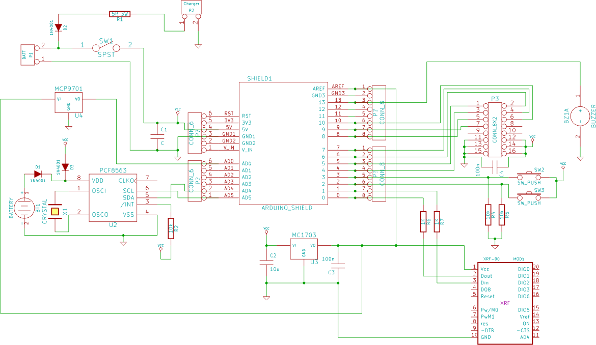
It is available here. It was developed by Joe Robertson. To keep the time when switched off, a back-up battery must be used. This can be any battery from 1V to 6V. I used a 3V CR2032 coin cell. You must be careful to ensure that the battery does not feed back to the arduino, nor that the ardunio power supply feeds back to the battery. To stop this you can use two general purpose diodes (I used 1N4001 as I have them around), as shown in the circuit diagram here: (Note: this circuit diagram is for an arduino shield I am making, hence it shows loads of other stuff) The library includes commands to set and read the time and date.
It also includes commands to set an alarm, although I have not implemented this into my device. You can use the various functions which include setDate, getWeekday etc etc (check the. cpp file in the rtc_ptc8583 library folder). When using the, write the name of the real time clock (in my case this was `rtc`) then add. command. For example: It was pretty easy, but I found a few problems (especially with another rtc library for the Ardunio which I could not get working correctly). This work has been done to be included as code on the arduino based LED dot matrix display hardware which I am planning on releasing as a kit for people to easily make their own LED displays.
Please I found that with the PCF8563 I was using was loosing around 30 seconds per day. This was obviously unacceptable. The data sheet explains that an accuracy of 300 seconds per year is obtainable, whihc is less than one second per day. Peter had commented on adding the trimmer capacitor (see comments below) which is mentioned in the PCF8564 data sheet.
I used a 8-30pF trimmer capacitor between OCS1 (pin 1) and ground. I then left the RTC running for a day or two. After testing I was now running 10 seconds per day fast! I found this application note (AN10652) from NXP who manufacture the RTC. Section 4 mentions about calibrating the accuracy of the RTC using an 8 digit frequency counter with an accuracy of 1ppm (part per million). To do this I first had to set the output clock (pin 7) to give an output the same as the oscillator frequency.
I was using 32. 768kHz crystal oscillator. I bought one of these ch 🔗 External reference
Related Circuits
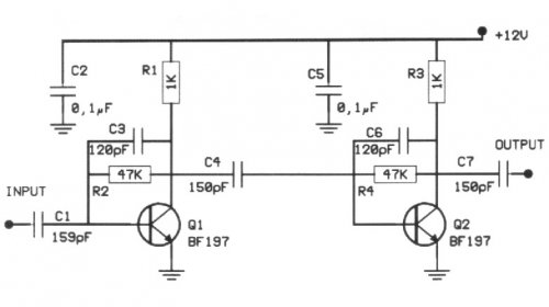
The following circuit illustrates a 20 dB VHF amplifier circuit diagram utilizing the BF197 transistor. Features include a simple circuit design. The 20 dB VHF amplifier circuit is designed to amplify very high frequency signals, making it suitable for applications...
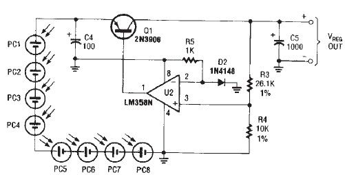
The circuit diagram illustrates a portable solar charger that utilizes an LM358N operational amplifier and a single transistor. This regulator delivers a constant output of 2.4 volts DC, suitable for powering small devices requiring energy from two AA battery...
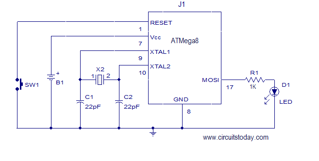
This article explains how to add a 32K external crystal/clock source to the Atmel AVR microcontroller Atmega8, including a circuit diagram and a C program. The Atmel AVR microcontroller Atmega8 is a popular choice for various embedded applications, often requiring...
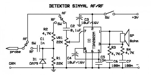
A signal detector circuit designed for detecting signals in both audio frequency (AF) and radio frequency (RF) ranges. This series is compact and straightforward to construct. The signal detector circuit operates by utilizing a combination of components such as diodes,...
The circuit diagram of a police siren utilizes two NE555 timer integrated circuits (ICs), each configured as an astable multivibrator. It can operate with a power supply ranging from 6 to 15V DC and produces a loud sound. An...
The TV transmitter presented generates a stream containing four TV programs and broadcasts it on a frequency compliant with the DTT standard. It is suitable for integration into an antenna system and can utilize audiovisual channels generated on-site or...
Warning: include(partials/cookie-banner.php): Failed to open stream: Permission denied in /var/www/html/nextgr/view-circuit.php on line 713
Warning: include(): Failed opening 'partials/cookie-banner.php' for inclusion (include_path='.:/usr/share/php') in /var/www/html/nextgr/view-circuit.php on line 713