
Audio Stereo Mixer circuit
R1-8-31-32=3.3Kohms C1-4-7-9-12-17=10uF 16V IC1=TLC274
R2-7-27-30=100ohms C2-8=470nF 63V MKT IC2=TLC272
R3-4-9-10=1Mohms C3-24-27-28=100nF 63V MKT IC3=7805
R5-11-21-22-23-24=10Kohms C5-10=10pF ceramic D1=1N4007
R6-12-15-17=1Kohms C6-11=1uF 16V D2=LED 3mm
R13-14-19-20-28-29=47Kohms C13-16-20-21=47pF JF1-2-5-6=female jack 3.5mm stereo
R18-16-25-26=22Kohms C14-15-18-19=1uF 63V MKT JF3-4=RCA female plug
RV1=2X100Kohms Lin. C22-23-25=100uF 16V JF7=female jack 3.5mm mono
RV2-3=47Kohms log. C26=4.7uF 16V
RV4=2X47Kohms log. C29=470uF 25V All the resistors are 1/4W 1% metal film
The described circuit effectively utilizes the sound card's line input to accommodate two mono microphones, enhancing its functionality for audio mixing applications. The presence of adjustable gain stages for each microphone allows for fine-tuning of audio levels, which is essential for achieving balanced sound output. The use of operational amplifiers (IC1 and IC2) facilitates signal processing, ensuring that the mixed audio maintains clarity and quality. The stabilization of voltage to +5V is crucial for protecting the sound card from potential damage due to overvoltage, thereby extending the longevity of both the sound card and the connected microphones. The component selection, including the use of metal film resistors for precision and ceramic capacitors for stability, reflects a thoughtful approach to circuit design aimed at optimizing audio performance.Most cards of sound in computer, are deprived stereo input for microphone, on the contrary have stereo input for high level [ Line ]. The circuit uses the input Line of card of sound, in order to we place a two mono stereo microphone, in the input of card of sound.
Simultaneously he is more functionnal, after we have the possibility of regulating the gain of stage of microphone and regulating the final level of sound externally and independent for each channel of microphone. This solution was selected in order to we can if we want mixing two mono microphones. Also exist the classic supply for Electret microphones. Simultaneously exist stereo input Line, with two choices plugs of input and regulation level of input with the RV4, making him mix of sounds from the microphones and the input Line, easy affair. The input A, use two plugs RCA [ JF3-4 ] and input B, use a classic stereo plug jack 3.5 mm of nail. The IC2A-B, make the addition of signals and they drive the stereo output, that becomes from the JF6 jack.
In JF7, we can give the supply, bigger than + 9Vdc, from a simple external power pack. This voltage is stabilised in + 5V, from the IC3. This low voltage was selected in order, to does not exist danger overdrive of card of sound. If the level, is not in the level that we want, we can change the prices of resistors R14-19 and R21 until R24, with other smaller or bigger, so that we change also the percentage of gain of proportional stage. Part List R1-8-31-32=3.3Kohms C1-4-7-9-12-17=10uF 16V IC1=TLC274 R2-7-27-30=100ohms C2-8=470nF 63V MKT IC2=TLC272 R3-4-9-10=1Mohms C3-24-27-28=100nF 63V MKT IC3=7805 R5-11-21-22-23-24=10Kohms C5-10=10pF ceramic D1=1N4007 R6-12-15-17=1Kohms C6-11=1uF 16V D2=LED 3mm R13-14-19-20-28-29=47Kohms C13-16-20-21=47pF JF1-2-5-6=female jack 3.5mm stereo R18-16-25-26=22Kohms C14-15-18-19=1uF 63V MKT JF3-4=RCA female plug RV1=2X100Kohms Lin.
C22-23-25=100uF 16V JF7=female jack 3.5mm mono RV2-3=47Kohms log. C26=4.7uF 16V RV4=2X47Kohms log. C29=470uF 25V All the Resistors is 1/4W 1% metal film 🔗 External reference
Related Circuits
This circuit is designed to demonstrate high-frequency high voltage, capable of producing voltages up to approximately 30 kV, depending on the transformer used. It is economical and straightforward to construct, primarily utilizing a standard TV flyback transformer. The circuit...
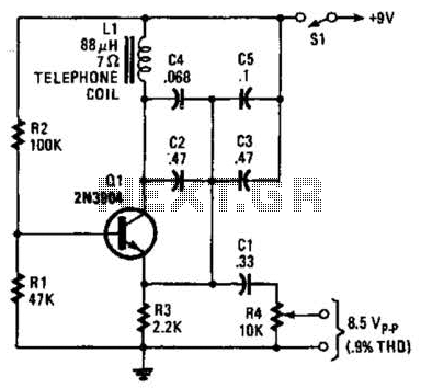
An 88 mH surplus telephone toroidal coil is utilized in a 1 kHz oscillator. It can provide up to 8 V peak-to-peak into a high-impedance load. The total harmonic distortion (THD) is 0.9%. The circuit employs an 88 mH toroidal...
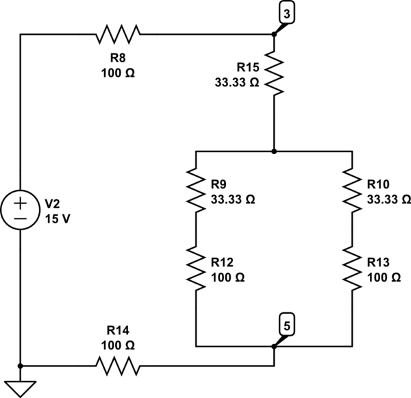
The Delta configuration of resistors R2, R3, and R4 is converted to a Wye (Y) configuration. This conversion is necessary because a voltage divider is typically employed in series circuits. The aim is to determine the total resistance in...
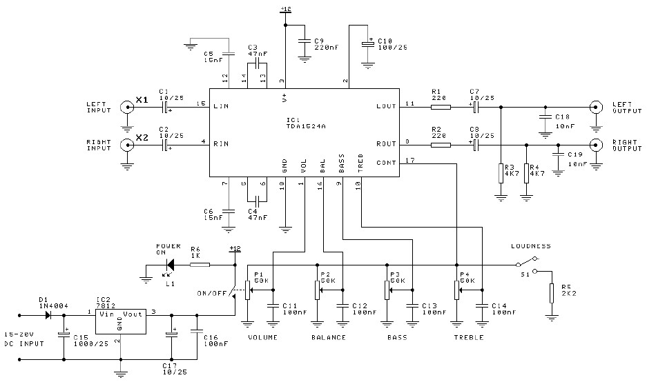
Preamplifier and tone control circuit based on the TDA1524A. The tone control circuit module is included in this preamplifier circuit, allowing for direct connection of the output channels to a stereo power audio amplifier circuit. This RIAA stereo preamplifier...
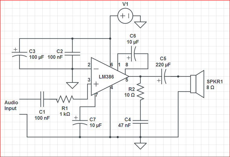
Initially, the circuit was connected to a 9V battery, which registered approximately 8.3 volts on a multimeter, within the operating voltage range for the LM386 as indicated in its datasheet. The output was characterized by significant noise, including crackling...
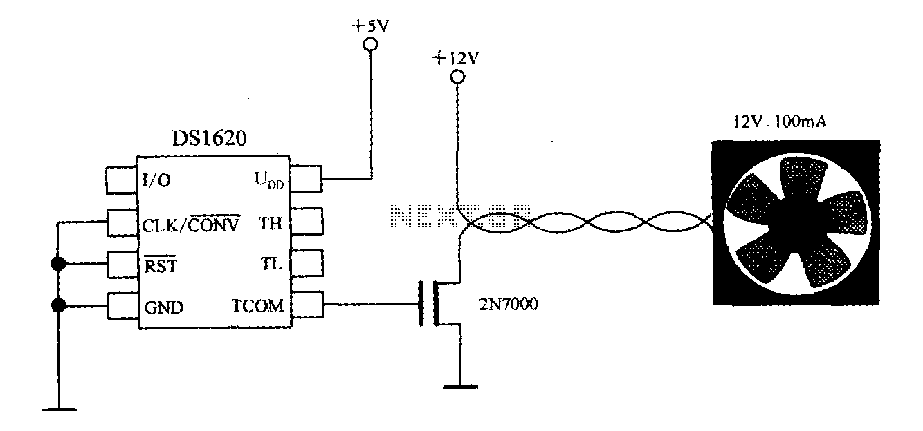
The DS1620, in conjunction with a microprocessor, is utilized to monitor temperature. By controlling the fan, the thermal conditions of the chip can be adjusted to establish a temperature control circuit as illustrated in the accompanying figure. The system...