
Car battery charger Automative car and motorcycle schematics
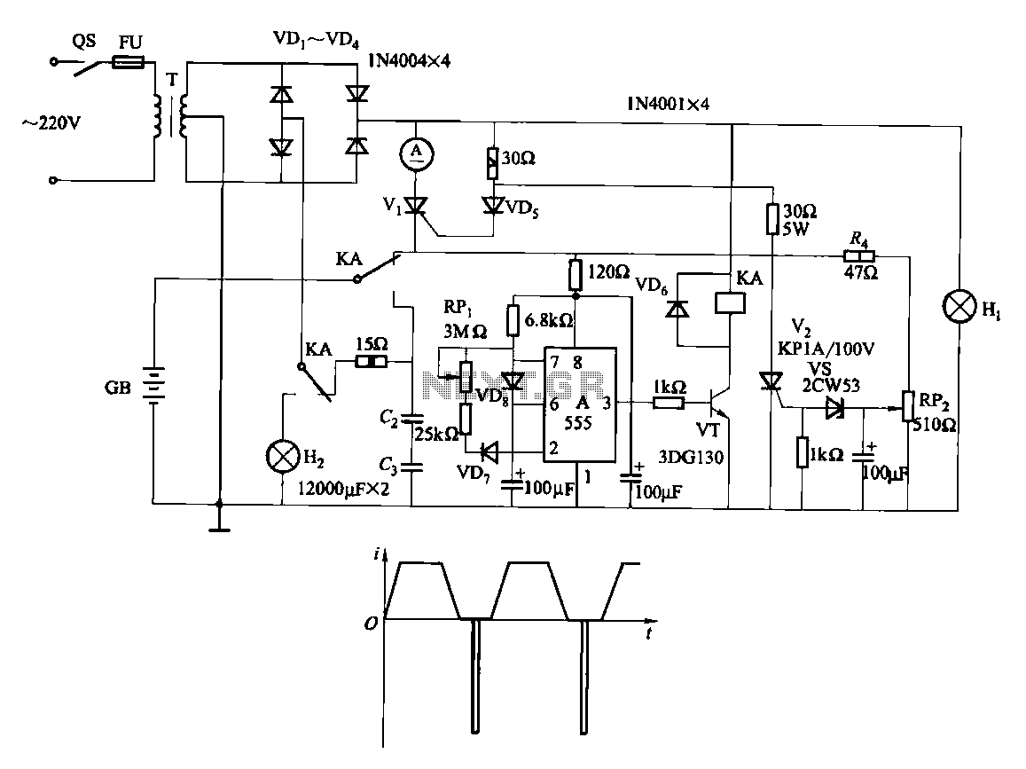
The circuit operates by directly connecting to a power supply, which provides the necessary voltage and current for charging a battery. The absence of a transformer indicates that the circuit is designed for a specific voltage level, typically from a DC power supply. Users may consider incorporating a transformer and rectifier if AC power is used, which would allow for voltage adjustment and conversion to DC.
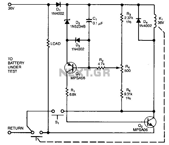
The charging mechanism is initiated by pressing the "Start" switch (S1), which completes the circuit and allows current to flow from the power supply to the battery. It is essential to ensure that the output terminals are correctly connected to the battery to prevent damage or inefficient charging.
Monitoring the circuit during its initial use is crucial, as it allows for the detection of any potential issues, such as overheating or excessive voltage, which could lead to battery damage or reduced lifespan. Implementing a simple voltage or current monitoring system can provide real-time feedback on the charging status, enhancing safety and efficiency.
For added protection, users may consider integrating a charge controller or a battery management system (BMS) that can automatically regulate the charging process, prevent overcharging, and optimize battery health. These systems often include features such as temperature sensors and automatic shut-off mechanisms, which further enhance the reliability of the charging circuit.The circuit was meant to be powered by a power supply, which is why there is no transformer, rectifier, or filter capacitors on the schematic. There is no reason why you cannot add these. To use the circuit, hook it up to a power supply/plug it in. Then, connect the battery to be charged to the output terminals. All you have to do now is push S1 ( the "Start" switch), and wait for the circuit to finish. The first time you use the circuit, you should check up on it every once and a while to make sure that it is working properly and the battery is not being over charged. 🔗 External reference
Related Circuits
The sensing circuit quickly disconnects the battery voltage and load when the voltage falls below a predetermined threshold. The one-way operation ensures that the circuit does not reconnect the load if the voltage subsequently rises above the threshold. Component...
When we step on the car's brake, then together with the classic rear STOP, the third STOP which is situated in the middle of the back half of the car also switches ON. This is the classic function, found...
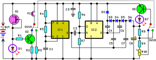
FET Q1 functions as a constant current generator, providing biasing for LED D1 and the base of Q2. This configuration ensures that D1 emits light at a consistent intensity, regardless of the battery voltage, which ranges from 3 to...

This circuit includes exit and entry delays, an instant alarm zone, an intermittent siren output, and an automatic reset feature. By incorporating external relays, it is possible to immobilize the vehicle and flash the lights. The alarm is activated...
A car alarm, in its simplest form, consists of one or more sensors connected to a siren. The most basic alarm features a switch on the driver's door, which is wired to trigger the siren when the door is...
Fast and efficient charging is significantly higher than conventional charging, achieving a current charge that is ten to several times greater. When the battery voltage reaches a predetermined level (known as the polarization point), polarization within the cell becomes...