
DC motor speed control circuit diagram of a song
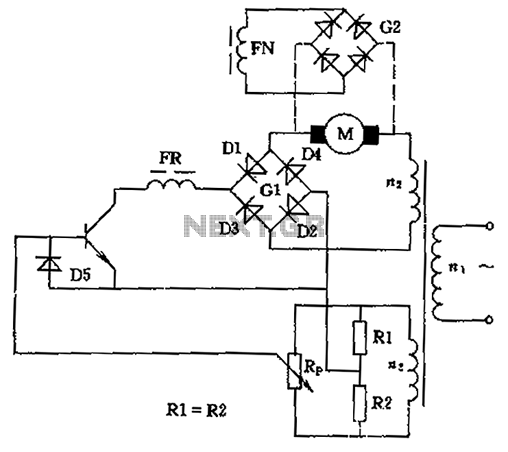
The circuit employs a rectifier bridge configuration (G1) to convert AC voltage from the transformer’s secondary winding into a usable DC voltage for the motor. This rectification process is crucial for providing a steady and reliable power supply to the motor, which is essential for consistent speed control. The control mechanism is further enhanced by the use of a sliding contact potentiometer (Rp), which functions as a variable resistor. Adjusting the position of the sliding contact alters the resistance in the circuit, thereby modifying the voltage supplied to the motor.
When the sliding contact is positioned at the midpoint, the circuit effectively disconnects the motor, stopping its operation. This feature serves as a safety mechanism, preventing unintended motor activation. Conversely, moving the sliding contact in either direction allows for the adjustment of motor speed and direction. The upward movement increases the voltage, causing the motor to rotate in the forward direction, while downward movement decreases the voltage, reversing the motor's rotation.
In practical applications, this circuit can be implemented in various settings, including robotics, conveyor systems, and other automated machinery where precise motor control is necessary. The design ensures that operators can easily manage the motor's performance, providing flexibility and adaptability to different operational requirements. Overall, this circuit represents a robust solution for controlling low-power DC motors with both speed and directional capabilities, making it a valuable component in electronic control systems. Circuit can be used to control low power DC motor, series motor or shunt motor speed and direction. Motor and rectifier bridge G1 series, and then connected to the grid transfo rmer secondary winding n2. If the output of the rectifier bridge fails, the motor stops, which is equivalent to the sliding contact potentiometer Rp in the middle position, if the upward or downward movement of the sliding contact, the motor will forward or reverse, it can control the motor operation.
Related Circuits
The motor vehicle steering flasher described in the example utilizes high-power transistors as electronic switches, and the circuit is simple and easy to construct. The motor vehicle steering flasher consists of the flash circuit with resistors R1-R3, a capacitor...
This is another kit in our self-sufficiency range. We also have a 12v fluoro inverter kit for those who need to operate 20watt to 40watt fluorescent lamps from a 12v supply. We will be introducing a number of kits...
This simple and inexpensive circuit built around a popular CMOS hex inverter IC CD4069UB offers four sequential switching outputs that may be used to control 200 LEDs (50 LEDs per channel), driven directly from mains supply. Input supply of...
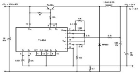
The circuit illustrates a TL494 pulse width modulated step-down converter schematic. This circuit allows for testing of line regulation, load regulation, output ripple, short circuit current, and efficiency under various input voltage conditions. A detailed table of these tests...
The circuit is designed to enable rapid changes in motor speed and direction by utilizing four outputs to drive a MOSFET H-bridge. The lower rail power MOSFETs are N-channel devices, while the upper rail MOSFETs are P-channel. All MOSFETs...
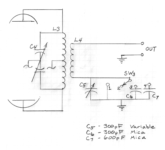
A series capacitor is most effective for low impedance loads, while a parallel capacitor is utilized for high impedance loads. The current standard is a 50-ohm antenna and coax system that requires a series capacitor for loading adjustment. With...