
Stormwise VLF Radio Electronic Project
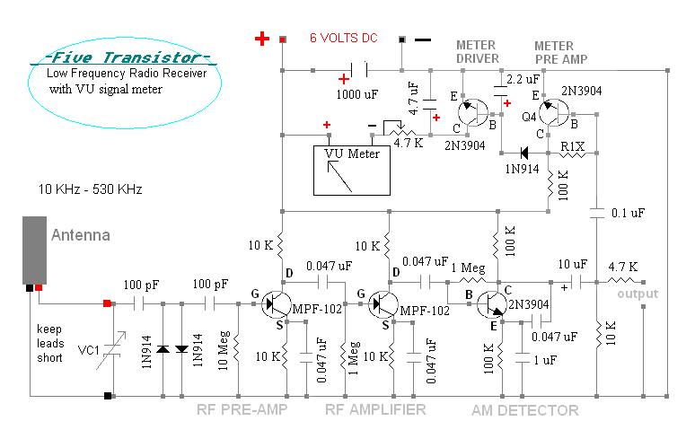
To construct the receiver, print the circuit diagram, scaling it down to fit the electronic components appropriately. The ideal size for the wooden board is approximately 8.5 inches by 5.5 inches. Safety goggles are essential during the soldering process, as molten solder can spatter. If soldering is unfamiliar, wire-wrap methods or a solderless breadboard can be utilized, ensuring the breadboard has a grounded shield base to prevent oscillation. Safety goggles are also necessary when clipping component leads or working with wires. Copper plates may be required for specific construction aspects.This radio receiver built on a piece of wood uses only 5 transistors but will receive longwave beacons and VLF beacons, depending on the antenna unit connected. Uses our AMVC-384 capacitor and one of our "C" antennas. This page is still under construction as of 07-08-2011. Our LOUDEST receiver yet. Features low noise FET transistors and improved A M detector. More photos to be added of completed unit. This 5 transistor low frequency radio receiver allows you to hear longwave beacons, broadcasts, and other signals in the range of 10 KHz to 530 KHz. It works just like an AM radio, a transistor demodulates AM signals. The receiver is designed for use with any of our high impedance antennas starting with the letter "C" in the model number, in the range of 10 KHz to 530 KHz.
The antenna`s tuning adjustment (via a variable or fixed-value capacitor, sold separately) is what selects the receive channel. This is a direct detection amplified "crystal" radio receiver. It does not generate RFI or use regeneration. It has no AGC circuit or noise-blanker, making it excellent for research applications (such as lightning detection).
Receiver will easily hear the lightning static that is always present in the lower frequency bands. Power the radio with a rechargeable 6 volt lantern battery. The radio will run a -very- long time, it only draws @ 10 mA, making it excellent for research uses where it has to run on solar or battery power only. The radio will also work on 9 volts without any problems. The parts and values are shown on the diagram above on this page. Standard values used. General parts available at any electronics store. Antenna and tuning capacitor available here at The transistors Q1 and Q2 are Field Effect Transistors (FET) MPF-102.
These are very high impedance transistors, similar to a vacuum tube in actual input and output performance and circuit design (but of course are solid-state devices not needing any filament heater or high voltages!). Two FET`s are shown, enough to boost the received signals for the 2N3904 transistor AM detector - giving loud volume into an audio amplifier.
An additional FET rf pre-amp could be added in (just ahead of the AM detector) for even more gain, but this could be too much sensitivity - producing overload and distortion. R1X is approximately 470 K ohms. This resistor will be different in each receiver depending on the initial sensitivity of the meter driver transistors.
If the value is too little then the meter will indicate when no signal is present. Adjust meter with R1X so it barely indicates with no signal present (short the antenna leads together so no signal is received). But first you will also need to set the full scale reading with the 4. 7 K-ohm variable resistor in the meter`s line. Shorting the first meter driver pre-amp`s BASE to ground will cause meter to read full scale - you can even add a battery test function by installing a momentary pushbutton switch here.
How to build it: Print out the above circuit diagram. Scale it down on your printer or photoshop program so that it is the right size, large enough for the electronic parts to fit the dots. This size is about 8 inches wide and 5 inches high. The wood board should be cut 8. 5 inches X 5. 5 inches. Obtain some safety goggles, you`ll be soldering and hammering nails and cutting a piece of wood (use a hand saw only).
Solder is molten metal and can spatter into your eyes. Do not solder without full eye protection. If you are not familiar with soldering practices, then it -IS- possible to use wire-wrap methods to build the receiver. You can also build the receiver on a solderless breadboard. Ask at Radio Shack store for this item. You`ll need the one with the grounded shield base, receiver -will- oscillate on these if not connected to the shield base.
You will still need the safety goggles when clipping part`s leads or working with the wires. Obtain some copper plate 🔗 External reference
Related Circuits
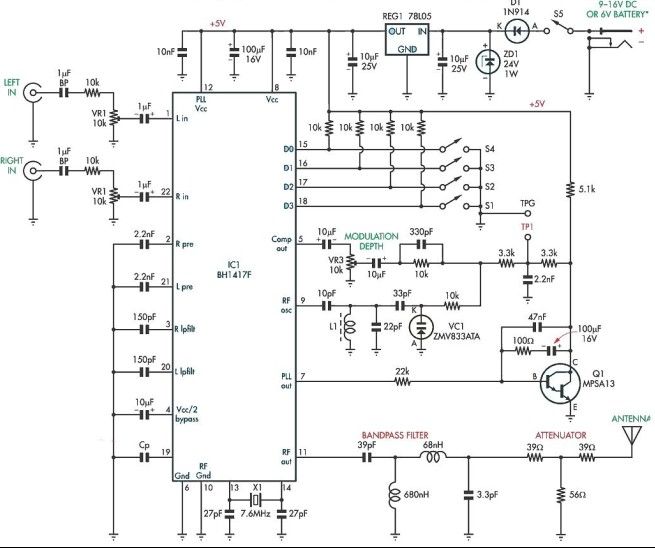
This stereo FM modulator circuit utilizes the BH1417F FM stereo transmitter integrated circuit (IC), which includes a stereo modulator for generating stereo composite signals and an FM transmitter for broadcasting an FM signal wirelessly. The stereo modulator produces a...
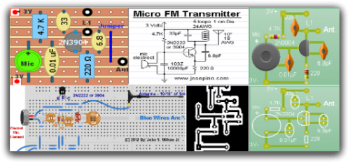
Radio-Circuits has elevated the standard with this website. Unlike any other circuit site on the internet, they have compiled ten of the most popular FM transmitter circuits. Radio-Circuits provides a comprehensive collection of FM transmitter circuits, showcasing a variety of...
The original BFO, a compact EICO 330 solid-state signal generator, effectively received a variety of distant longwave (LW) beacons. In late 2004 to early 2005, a new One-Active Device (1-AD) contest was introduced to complement the Crystal Set DX...
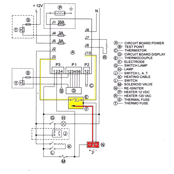
With the exception of pilot-type water heaters and some smaller LP/Electric refrigerators, modern LP appliances in RVs are controlled by electronics. Modern LP (liquefied petroleum) appliances utilized in recreational vehicles (RVs) have largely transitioned to electronic control systems, enhancing their...
A simple circuit for monitoring the fuel level in vehicles. It provides an audiovisual indication when the fuel level drops alarmingly below the reserve level, assisting in fuel management. The fuel level monitoring circuit typically consists of a fuel level...
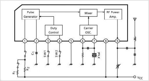
TB6556FG is a 3-phase full-wave sine-wave PWM brushless motor controller. It features sine-wave PWM control and includes a built-in triangular-wave generator with a carrier cycle defined as fosc/252 (Hz). The device also offers a built-in lead angle control function...