
Indicators Projects
The fuel level monitoring circuit typically consists of a fuel level sensor, a microcontroller or comparator, and an output stage that drives an indicator. The fuel level sensor, often a float switch or a resistive level sensor, detects the fuel level in the tank and converts it into an electrical signal. This signal is then sent to a microcontroller or comparator, which continuously monitors the input.
When the fuel level falls below a predetermined threshold, indicating that the fuel is nearing the reserve level, the microcontroller activates an output stage. This output stage may include LEDs for visual indication and a buzzer or speaker for auditory alerts. The circuit may also incorporate a debounce mechanism to prevent false triggering due to fluctuations in the fuel level.
To ensure proper operation, the circuit should be powered by the vehicle's electrical system, typically 12V DC. It is essential to include protection components such as diodes to prevent reverse polarity and voltage spikes that could damage the circuit. Additionally, the use of capacitors can help filter any noise from the power supply, ensuring stable operation.
Overall, this fuel level monitoring circuit enhances vehicle safety and efficiency by providing timely alerts to the driver, allowing for proactive fuel management and reducing the risk of running out of fuel unexpectedly.A simple circuit for monitoring the fuel level in vehicles. It gives an audiovisual indication when the fuel level drops alarmingly below the reserve level, helping you to read more †’ 🔗 External reference
Related Circuits
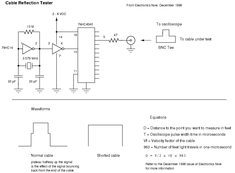
Another method of testing the received signal strength on a Symphony-based wireless network is with a homebrew signal meter. The National LMX2240 Intermediate Frequency Receiver has a pin called "RSSI Out." RSSI stands for Relative Signal Strength Indicator and...
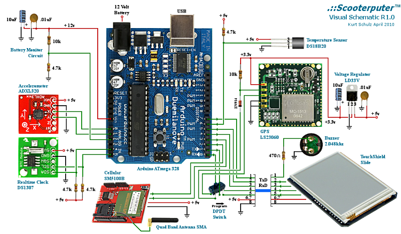
Powerful for its size and cost, and extremely easy to learn and use. A voltage monitor was added to a scooter to warn when the battery might need recharging, instead of waiting for the electric starter to fail. An...
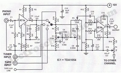
This Hi-Fi stereo preamplifier circuit is constructed using the TDA1054 integrated circuit (IC) from SGS. The TDA1054 is housed in a 16-pin DIL package and incorporates two separate preamplifier circuits. It is characterized by low noise and minimal issues...
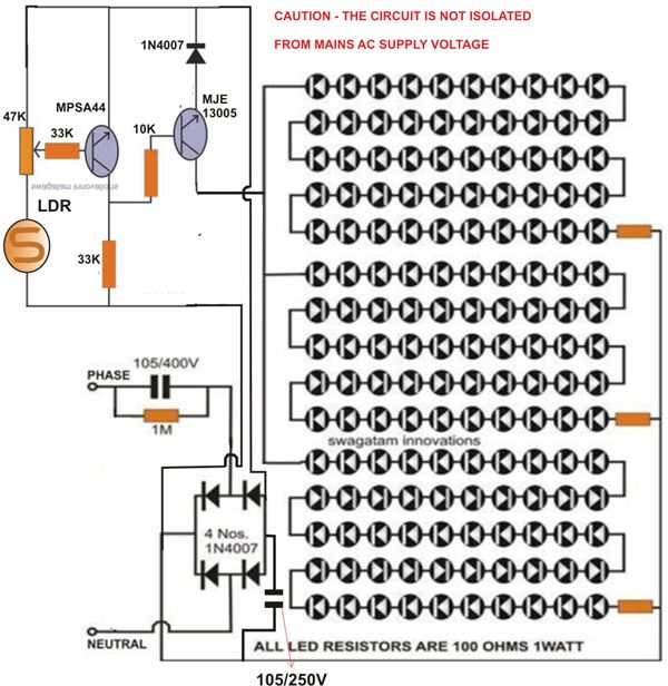
At times, it is quite frustrating to see street lights remaining switched on even during broad daylight. The current circuit for an automatic night light can effectively address this issue. This article explains how to construct such a system....
This project was inspired by a desire to create something unique rather than with the expectation of it becoming a practical transmitter. At the time of writing, the project is in the breadboarding phase, and a decision has yet...
This document discusses the use of small microcontrollers, such as those from the PIC and Atmel series, which typically operate at 5V and require less than 100mA for complete system functionality. Some PICs can function at lower voltages, such...