
Mobile Controlled Robot without microcontroller

The mobile-controlled robot operates through a wireless communication interface, typically utilizing Bluetooth or Wi-Fi technology. The control system is designed to receive commands from a smartphone application, which serves as the user interface. The smartphone sends control signals to the robot, enabling it to perform various functions such as movement, obstacle avoidance, and task execution.
The core components of the robot include a microcontroller, motor drivers, and sensors. The microcontroller acts as the brain of the robot, processing incoming signals from the smartphone and translating them into actionable commands for the motors. Motor drivers are essential for controlling the speed and direction of the robot's wheels or tracks, allowing for precise maneuverability.
Sensors such as ultrasonic or infrared are often integrated into the robot to facilitate obstacle detection and navigation. These sensors provide real-time feedback to the microcontroller, enabling the robot to adjust its path and avoid collisions.
Power supply considerations are also crucial; the robot typically operates using rechargeable batteries, which must be selected based on the required voltage and current ratings for the motors and electronics.
Overall, a mobile-controlled robot presents a versatile platform for various applications, including education, entertainment, and research, demonstrating the integration of mobile technology with robotics.A Mobile Controlled Robot is a mobile device, which provides wide-range of wireless control ability to your robot unless your cell phone gets out of signal.. 🔗 External reference
Related Circuits
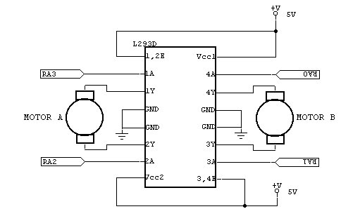
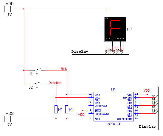
The robot consists of modules controlled by a main controller. The main microcontroller is an 18-pin, 8-bit PIC16F84 Flash microcontroller operating at 4MHz. The microcontroller is programmed in assembly language. The controller is connected via I/O pins to the...
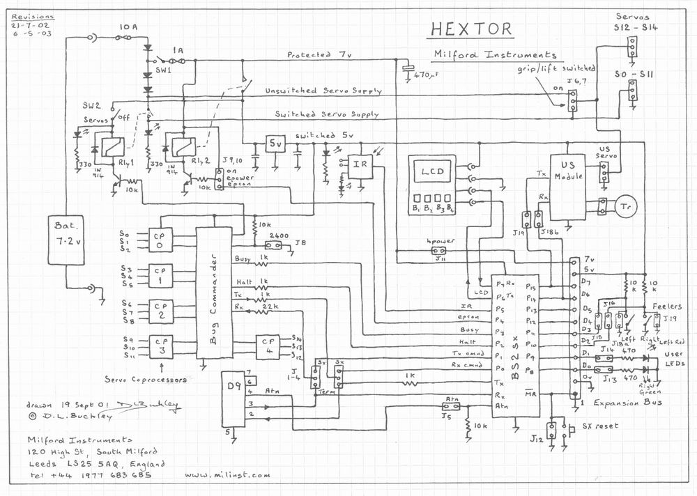
The circuit includes multiple connections for a BOS (Basic Operating System) processor. It has a serial connection for transmitting data to the BOS processor (pin 0) and receiving data from it (pin 1). Pin 2 is used to supply...
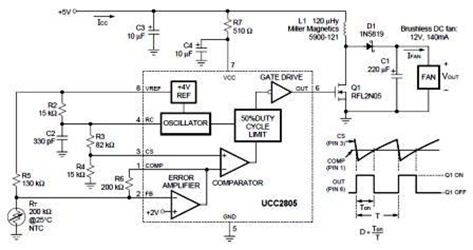
A temperature-controlled pulse-width-modulator (PWM) boost converter circuit diagram is illustrated in the following figure. This boost converter is designed to operate a 12V fan using a 5V supply while maintaining temperature control. The temperature-controlled PWM boost converter circuit operates by...
The WS2512-TR1G is a Wide-band Code Division Multiple Access (WCDMA) Power Amplifier (PA) designed as a fully matched 10-pin surface mount module, specifically developed for WCDMA handset applications. This power amplifier module operates within a frequency range of 1920-1980...
National Instruments Multisim now features microcontroller unit co-simulation capabilities, enabling the inclusion of a microcontroller, programmed in assembly or C code, within SPICE-modeled circuits. The MCU functionality in Multisim allows students, educators, and professional users to program MCUs in...
The circuit is compatible with all 2323 chips, but it is optimized for the AT90LS2323, which operates at a voltage range of 2.7 to 6 volts. The microcontroller utilized in this design is the AT90S2323, which functions effectively within...