
Led Clock using PIC16F84
The described digital LED clock circuit utilizes a minimal number of components, making it a cost-effective solution for timekeeping applications. The core of the circuit is a PIC microcontroller, which serves as the brain of the clock, managing the timekeeping functions and controlling the display output.
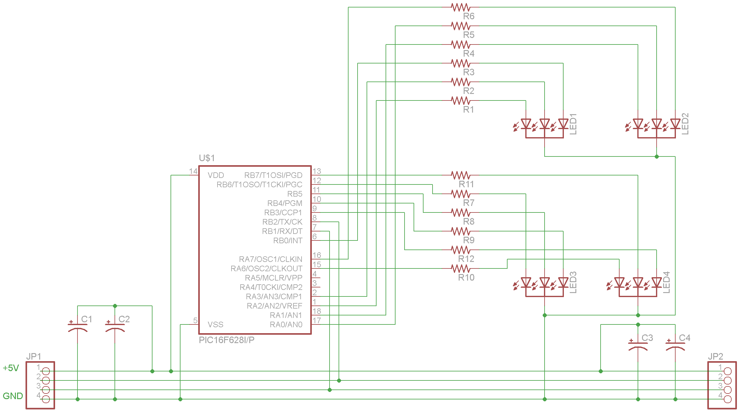
The circuit employs four seven-segment displays, which can be configured as either common anode or common cathode types. The selection between these two types is made by connecting pin 3 of the microcontroller to either the positive or negative supply, depending on the display type chosen. This flexibility allows for adaptability in various applications depending on available components.
Two capacitors, each rated at 30 pF, are used in conjunction with a crystal oscillator (xtal) to establish a stable clock frequency. It is crucial to select the capacitor values according to the specifications provided by the crystal manufacturer to ensure optimal performance and accuracy. Special attention should be given to the layout of the connections to the crystal, as minimizing the length of these connections is essential for maintaining the timing accuracy of the clock.
The circuit also includes two normally open (n.o.) switches, which can be used for user input, such as setting the time or switching between different modes of operation. The functionality of these switches can be programmed into the microcontroller to enhance user interaction.
Resistors play a vital role in the circuit, with three resistors used for current limiting and pull-up or pull-down configurations as necessary. Notably, for the PIC 16F84 microcontroller, a 10 kΩ resistor is required on pin 4, while this pin remains unconnected when using the 16F628 variant.
It is also important to note that the minute displays are oriented upside down, which may require additional consideration during the design phase to ensure readability and correct display orientation.
Overall, this digital LED clock circuit exemplifies a straightforward yet effective design, suitable for both educational purposes and practical applications in timekeeping devices. Proper attention to component specifications, layout, and configuration will yield a reliable and functional clock.Using only 2 capacitors, 3 resistors, 4 seven-segment Display, 1 xtal, 2 switches n.o. and 1 Microcontroller PIC, you can build this Digital Led Clock. you can use common anode or common cathode display, just select the display type. Here is the pinout information: Pin 3 defines the display type. If you will use common cathode display, connect to negative. For common anode, connect to positive. Here is a example circuit:
Please note: the pin 4 requieres a 10k resistor ONLY for 16F84. On 16F628 is not connected. The minutes displays are upside down. For the capacitors, I used 30pf. You have to read the xtal manufacturer specifications to know the capacitor value recommended. Short connections on xtal is a must to keep accuracy.
🔗 External referenceRelated Circuits
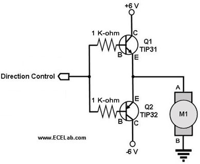
The following circuit illustrates a two-transistor DC motor driver circuit diagram. This circuit utilizes the TIP32 transistor. Features: operates in... The two-transistor DC motor driver circuit is designed to control the operation of a DC motor using two NPN transistors,...

The circuit illustrated briefly flashes an LED to attract attention and remains illuminated as long as power is supplied. The circuit utilizes the well-known 555 timer integrated circuit (IC) configured as a standard astable multivibrator with resistors RA, RB,...
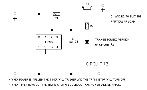
The goal is to create a small light that is activated by motion and stays illuminated for 20 seconds before turning off. For example, when the light is picked up, it illuminates, and when placed back down, it remains...

The multifunction frequency meter is an instrument that can measure various parameters on a single display using an 8-digit 7-segment LED. The controls measure... The multifunction frequency meter is designed to provide accurate measurements of frequency, voltage, current, and other...
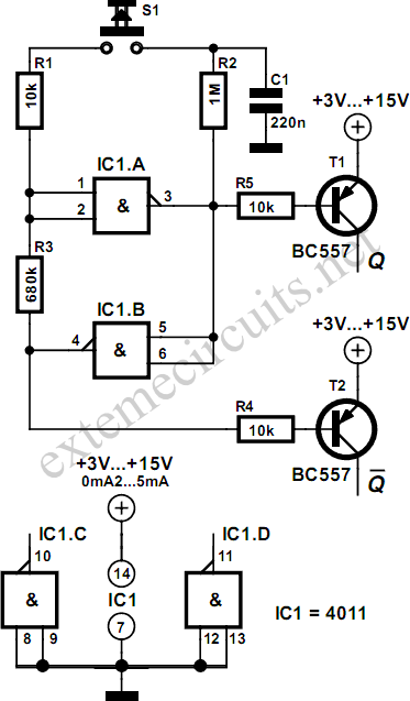
Using just two NAND or inverter gates, it is possible to build a D-type (or toggle) flip-flop with a push-button input. At power-up, the output of gate N2 is at a logical 1, ensuring that transistor T2 is switched...
The complete schematic for the driver is provided. A PIC16F628 microcontroller has been selected due to its low cost, internal oscillator (4 MHz), and built-in USART. It is important to note that there is an error in the schematic;...