
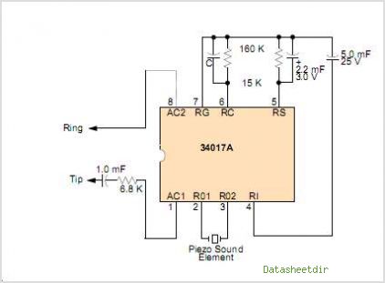
Subaudible tone encoder
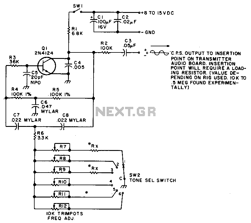
The twin-T oscillator is a specific type of electronic oscillator that utilizes a twin-T network configuration to produce audio signals at subaudible frequencies. The circuit typically consists of two T-shaped networks composed of resistors and capacitors, which are configured to create phase shifts necessary for oscillation.
In this design, the oscillator is capable of producing six different frequencies, specifically within the range of 93 Hz to 170 Hz. The selection of these frequencies is achieved through the adjustment of component values or through the use of switches that alter the resistor and capacitor configurations, enabling the user to choose from three distinct frequency ranges.
The operation of the twin-T oscillator is based on the principle of feedback, where a portion of the output signal is fed back into the input in a manner that sustains oscillation. The stability and accuracy of the generated frequencies are influenced by the tolerance of the components used, particularly the resistors and capacitors, as well as the quality of the power supply.
In practical applications, such oscillators can be utilized in sound synthesis, alarm systems, and various audio applications where low-frequency tones are required. The ability to produce multiple preset tones makes this oscillator versatile for different uses, including experimental sound design and audio testing. Proper grounding and shielding are essential in the circuit design to minimize unwanted noise and ensure signal integrity.This twin-T oscillator produces six preset subaudible tones from 93 to 170 Hz in three ranges. 🔗 External reference
Related Circuits
This is an improved version of the audio interface commonly used to connect a computer soundcard to a transceiver's receive and transmit audio circuits. This kind of interface is used by computer programs that send and receive SSTV, RTTY,...
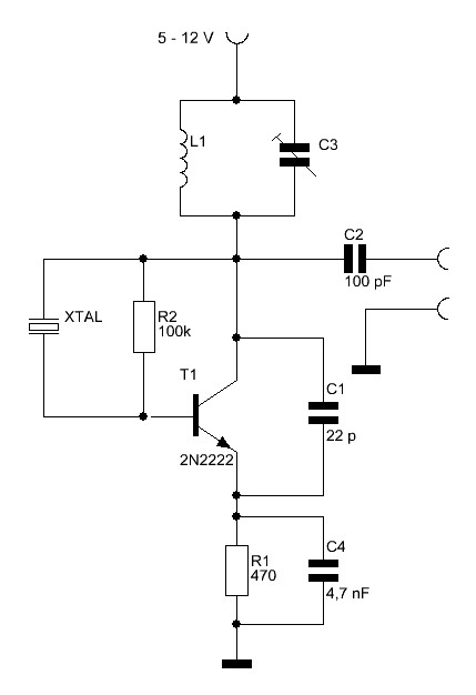
Crystals with higher frequencies than approximately 30 MHz are predominantly overtone crystals. These crystals are designed to operate at an odd multiple of their fundamental frequency. However, they do not resonate at their overtone frequency without assistance; the oscillator...
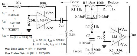
This topic continues from the more general Passive Tone Control circuit, which begins using only passive filters. This circuit follows the previous design, although the component values are different and in an alternate configuration. An audio tone control combines...
It is widely recognized that power-saving regulations necessitate very low power consumption during standby conditions for all equipment continuously connected to mains power. In the standard version of the power supply, standby power consumption is approximately 9.0 W for...
The circuit diagram is designed to control audio tone. This circuit utilizes the TDA 1524 tone control integrated circuit (IC), which encompasses controls for balance, bass, treble, and volume within a single component. A potentiometer is employed in series...
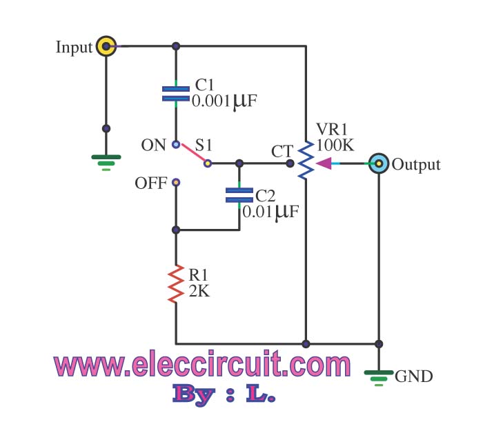
The passive tone control circuit is designed to adjust the bass without expansion, utilizing resistors (R) and capacitors (C). It functions as a frequency filter and is easy to construct, requiring no external power supply. This circuit can be...
Warning: include(partials/cookie-banner.php): Failed to open stream: Permission denied in /var/www/html/nextgr/view-circuit.php on line 713
Warning: include(): Failed opening 'partials/cookie-banner.php' for inclusion (include_path='.:/usr/share/php') in /var/www/html/nextgr/view-circuit.php on line 713