
Tone Control Using TDA1524
The TDA 1524 is a versatile tone control IC widely used in audio applications for its ability to integrate multiple functions into a single package. It incorporates a preamplifier, bass, treble, and balance controls, providing a comprehensive solution for audio signal processing. The IC operates with an external power supply, typically ranging from 12V to 18V, and is designed to handle input signals from various audio sources.
In the schematic, the audio input is fed into the TDA 1524, where it is processed through the internal circuitry. The potentiometer connected in series allows for real-time adjustments to the audio signal. By varying the resistance, the voltage at the center terminal of the potentiometer changes, which in turn alters the gain and frequency response of the audio output. This feature enables users to tailor the sound to their preferences, enhancing the listening experience.
The output from the TDA 1524 can be connected to a power amplifier or directly to speakers, depending on the design requirements. It is essential to implement proper filtering and decoupling capacitors in the circuit to minimize noise and ensure stable operation. Additionally, it is advisable to include a bypass capacitor close to the power supply pins of the IC to further enhance performance.
Overall, this circuit diagram serves as an effective tool for audio tone control, providing flexibility and ease of use through the integration of the TDA 1524 IC and the potentiometer configuration.Circuit diagram is one of the circuit diagram to set the tone. Circuit diagram This is controlled by using the tone control IC TDA 1524 the type that includes all of the balance of bass and treble volume in one IC TDA 1524 a. You can setting a potentiometer, in several series, changes the voltage on the center potensio ic work
🔗 External reference
Related Circuits
The circuit begins with a step-down mains transformer featuring a secondary winding rated at 24 V/3 A, which connects across the input points at pins 1 and 2. The quality of the output supply is directly related to the...
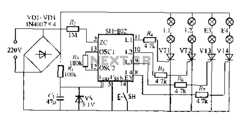
A digital integrated circuit simplifies the response process significantly. The diagram illustrates a circuit comprising four responder groups. The digital integrated circuit described serves as a crucial component in various electronic systems, primarily focusing on enhancing response efficiency. It comprises...
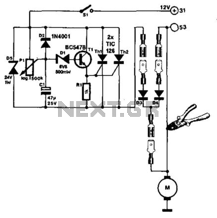
The windshield wiper interval circuit described here is compact and notable for utilizing two thyristors instead of a relay. It features only two connections and operates smoothly, even with multistage wiper circuits. The wire connecting the wiper motor to...
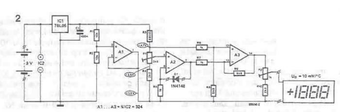
A simple thermometer can be constructed using operational amplifiers and a standard or protective diode, such as the 1N4148, as depicted in the electronic diagram below. A constant reference voltage is supplied to the non-inverting input of the operational...

This oscillator may contain several switched crystals to provide channelized operation. A buffer amplifier may be added if desired. The oscillator described is designed to utilize multiple switched crystals, enabling it to operate across various frequency channels. This feature is...
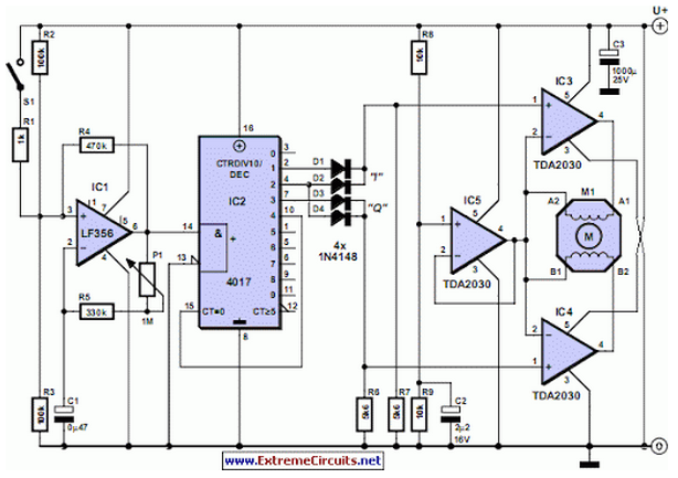
Stepper motors are available in several versions and sizes with a variety of operating voltages. The advantage of this general-purpose controller is that... Stepper motors are electromechanical devices that convert electrical energy into precise mechanical movement. They are widely used...
Warning: include(partials/cookie-banner.php): Failed to open stream: Permission denied in /var/www/html/nextgr/view-circuit.php on line 713
Warning: include(): Failed opening 'partials/cookie-banner.php' for inclusion (include_path='.:/usr/share/php') in /var/www/html/nextgr/view-circuit.php on line 713