
Subcutaneous Transmitter

The encapsulation of the device consists of an epoxy center with a silicone coating. The leads are made from silicone-coated stainless steel, while the antenna is composed of 7 G—100 m stainless steel stranded wire. The analog leads are 400-μm springs made from 100-μm diameter 302 stainless steel, with the bare tips of the leads tinned with solder. The A3013A transmits 512 samples per second for over nine weeks before the battery depletes. The transmitter can be turned on and off at any time using a magnet, even when implanted in an animal. When switched off, the transmitter will deplete its battery in thirty-two weeks.
The A3013 is encapsulated in epoxy and coated with silicone, resulting in an inert, waterproof, vacuum-resistant, and easy-to-clean design. The encapsulation is robust enough to remain unharmed inside an animal for nine weeks and can tolerate temperatures ranging from -40 °C to +125 °C. Once the battery is exhausted, the transmitter must be discarded as the epoxy encapsulation cannot be opened for battery replacement.
The A3013 is battery-powered, providing differential reception for its first input using only two wires. It features a single analog input configured as a two-wire differential with a 10-MΩ input impedance. The input's dynamic range is 9 mV, and it includes a one-pole high-pass filter and a three-pole low-pass filter, yielding a bandwidth of 0.2 Hz to 160 Hz. Within this bandwidth, the electrical noise on the input is 12 μV, which corresponds to 80 of the transmitter's sixteen-bit ADC counts.
The radio frequency transmissions of the A3013 utilize most of the bandwidth available in the 902-928 MHz ISM band. Multiple A3013 devices can operate in the same vicinity and share a common receiving antenna. The brief nature of the A3013's radio frequency transmissions minimizes the likelihood of collisions between transmitters. In instances where collisions do occur, the data acquisition system is capable of eliminating corrupted measurements from the data stream, resulting in minimal degradation of signal quality. Up to eight A3013 devices can simultaneously share the same receiving antenna while maintaining a signal bandwidth of 160 Hz. If the signal bandwidth is reduced to 40 Hz, it is possible for up to forty transmitters to share the same antenna.
The A3013 employs stainless steel springs for its analog leads and stranded stainless steel cable for its antenna, all insulated with silicone. This design ensures durability within a live animal for several months, where the wires are subjected to millions of repetitive stress cycles in tension, torsion, and compression. The A3013A is a single-channel transmitter featuring three external connections: X+ for the positive input of channel X, X- for the negative input, and RF for the antenna. Key components include the battery, a magnetic reed switch, a programmable logic chip, and a 100-nF AC capacitor.The Subcutaneous Transmitter (A3013) transmits biometric signals from within the body of a live animal. It is the implantable transmitter component of our Subcutaneous Transmitter System. The A3013 detects biometric signals with flexible 150-mm leads, digitizes them, and transmits them as bursts of 915-MHz radio-frequency power through a 50-mm an
tenna. A nearby antenna receives the radio-frequency bursts and records the biometric signals. Within a faraday enclosure, such as our FE2A, the operating range of the A3013 is limited only by the size of the enclosure. Without a faraday enclosure, operating range varies from 25 cm on the eighth floor of an office building in London to 200 cm in a basement laboratory in Boston.
We designed the A3013 to monitor EEG in rats. Figure: Encapsulated Subcutaneous Transmitters A3013A-E. Click on image for higher-resolution. The encapsulation consists of an epoxy center with a silicone coating. The wires are silicone-coated stainless steel. The antenna is 7 G— 100 m stainless steel stranded wire. The analog leads are 400- m springs made out of 100- m diameter 302 stainless steel. The bare tips of the leads are tinned with solder. The A3013A transmits 512 samples per second for over nine weeks before its battery runs out. We can turn the transmitter on and off at any time with a magnet, even when the transmitter is implanted in an animal. When turned off, the transmitter will run its battery down in thirty-two weeks. (See Battery Life for more details. ) The A3013 is encapsulated in epoxy and coated with silicone. The resulting encapsulation is inert, water-proof, resistant to vacuum, easy to clean, tough enough to survive unharmed inside an animal for nine weeks, and tolerant of temperatures from ’40 °C to +125 °C.
Once the battery is exhausted, however, the transmitter must be discarded. There is no way to break open the epoxy encapsulation to replace the battery. (See Encapsulation for more details. ) Because the A3013 is battery-powered, it provides perfect differential reception for its first input with only two wires. The A3013A has a single analog input, which takes the form of a two-wire, differential 10-M © input impedance.
The input`s dynamic range is 9 mV. A one-pole high-pass filter and a three-pole low-pass filter provide a bandwidth of 0. 2 Hz to 160 Hz. Within this bandwidth the electrical noise on the input is 12 V, which is 80 of the transmitter`s sixteen-bit ADC counts. (See Analog Inputs for more details. ) The A3013`s radio-frequency transmissions occupy most of the bandwidth available in the 902 ’928 MHz ISM Band.
Multiple A3013`s operating in the same area can share the same receiving antenna. The A3013 radio-frequency transmissions are so brief that collisions between transmitters are rare. When collisions do occur, the data acquisition system eliminates the corrupted measurements from the data stream. The resulting degradation in signal quality is minimal. Eight A3013s can share the same receiving antenna and all maintain a signal bandwidth of 160 Hz simultaneously.
If we drop the signal bandwidth to 40 Hz, forty transmitters could share the same antenna. (See the Collisions section of Subcutaneous Transmitters. ) The A3013 uses stainless steel springs for its analog leads, and stranded stainless steel cable for its antenna. All are insulated in silicone. The leads and antenna are designed to survive in a live animal for several months, where wires are subject to millions of repetetive stress cycles in both tension, torsion, and compression.
(See Flexible Wires for more details. ) Figure: Naked Subcutaneous Transmitter (A3013A-N), Top and Bottom Sides. The A3013A is a single-channel transmitter with three external connections: X+ is the positive input for channeld X, X ’ is the negative input, and RF is the antenna. Marked are (1) battery, (2) magnetic reed switch, (3) programmable logic chip, (4) 100-nF AC 🔗 External reference
Related Circuits

The current system is a dedicated 486 computer running Homeseer software. The hardware setup includes a CM11A computer-to-X10 interface along with several appliance and lamp modules. Additionally, there is a homebrew infrared (IR) system that connects the computer to...
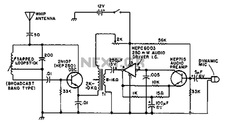
A circuit diagram of the T1 is a low-impedance output transformer, featuring a 5000-8 ohm resistor. The T1 low-impedance output transformer is designed to match the output of audio amplifiers to the impedance of loudspeakers, ensuring optimal power transfer and...

With the equipment ready for operation, the main line switch (S-831), the emergency switch (S-12), and the main line contactor contacts (K-831B) are all closed. The keying relay main contacts (K-1C) ground the center tap of the MO filament...
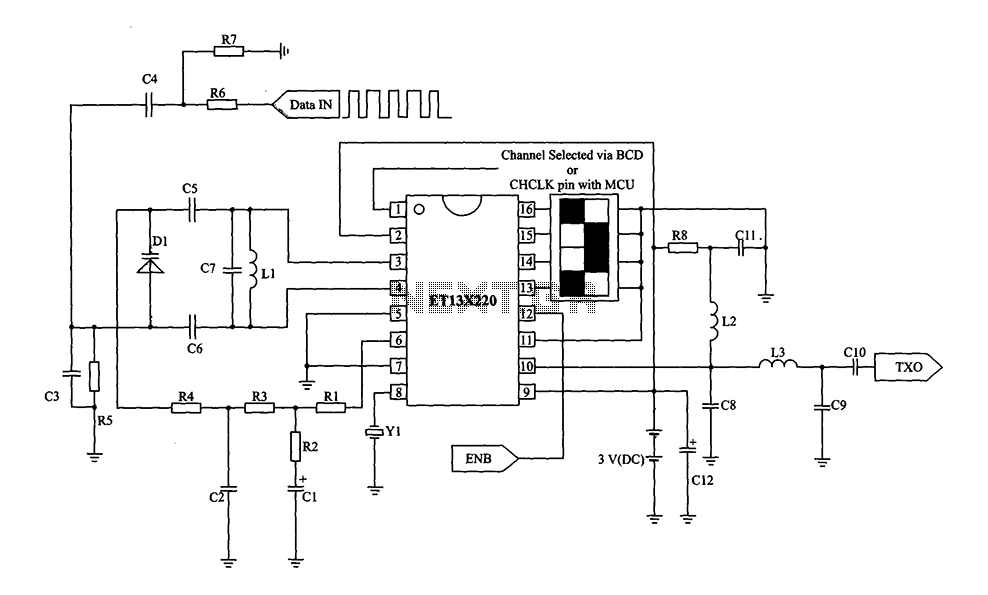
The ETl3X220 is connected to a low-cost single-chip RF transmitter, capable of supporting 10 communication channels for wireless mouse, keyboard, and other communication products. The main technical features include analog FM or digital FSK modulation with a channel spacing...
Here's PLL FM transmitter circuit from china. This circuit uses the familiar 2SC1971 for final power amplifier stage. The PLL controller of the FM transmitter use SAA1057 and PIC16F628 (download HEX file). More: If want to change the active...

Momentary output: One of the relays RE1...RE4 is ON as long as CH1---CH4 is pressed from transmitter. Latch output: when one of channels CH1...CH4 is pressed from transmitter RE1...RE4 are ON as long as other CH is pressed from...