
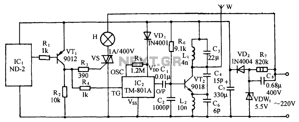
1-2 MHz radio transmitter circuit diagram
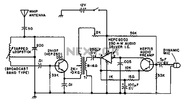
The T1 low-impedance output transformer is designed to match the output of audio amplifiers to the impedance of loudspeakers, ensuring optimal power transfer and minimal signal loss. The transformer typically features primary and secondary windings that are configured to handle the specified impedance ratio of 5000 ohms on the primary side to 8 ohms on the secondary side.
In the schematic, the primary winding is connected to the amplifier output, while the secondary winding connects to the speaker load. The low-impedance design allows for efficient power delivery, making it suitable for various audio applications, including guitar amplifiers and hi-fi audio systems.
The circuit may also include additional components such as capacitors for filtering and protection, ensuring that high-frequency signals do not distort the audio output. Furthermore, the physical layout of the transformer should consider factors such as magnetic coupling and core material to optimize performance and minimize losses.
Overall, the T1 output transformer plays a critical role in audio signal integrity, providing a reliable interface between the amplifier and the speaker system while supporting the desired sound quality.A circuit diagram of the T1 is a low-impedance output transformer, it comes with 5000-8 ohm resistor.
Related Circuits
A 90-degree phase shift can be achieved in VHF applications using an IQ oscillator that employs two logic integrated circuits (ICs). The 74AC04 inverter serves as the oscillating circuit, while components C5 and R6 function as the phase shifter....
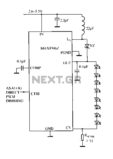
Driving a series of white LEDs allows for a consistent current to flow through each LED, resulting in uniform brightness. However, a disadvantage of this series configuration is that the driving voltage must account for the forward voltage drop...
The microphone amplifier/modulator is built around the LM324, which is a quad operational amplifier that provides sufficient quality amplification for the voice captured by the condenser microphone. The LM324 is a versatile quad op-amp that consists of four independent, high-gain,...
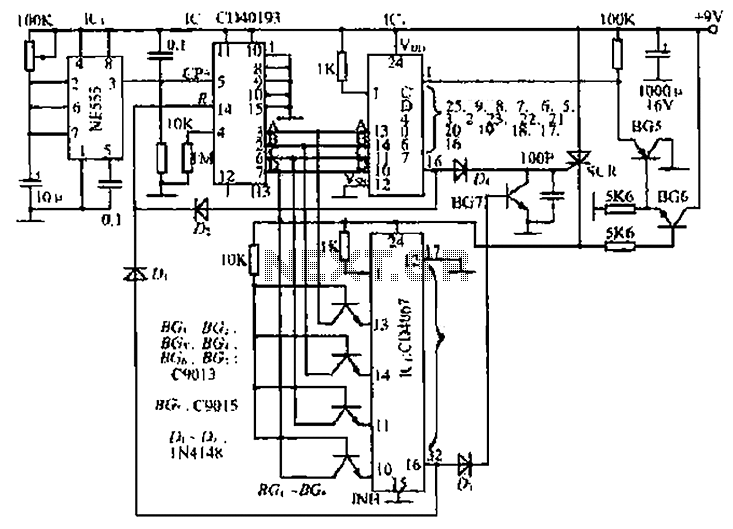
The circuit consists of an oscillator, a counter, and an Iseki circuit divided into three parts. The oscillator is based on the NE555 timer and several external RC components, generating a pulse signal for the counter. The instantaneous power...
The circuit includes a comprehensive array of components such as vibration sensors, a follower, a lamp relay control circuit, a voice sounding circuit, a high-frequency oscillation circuit, and an AC rectifier buck power supply circuit. The vibration sensor is...
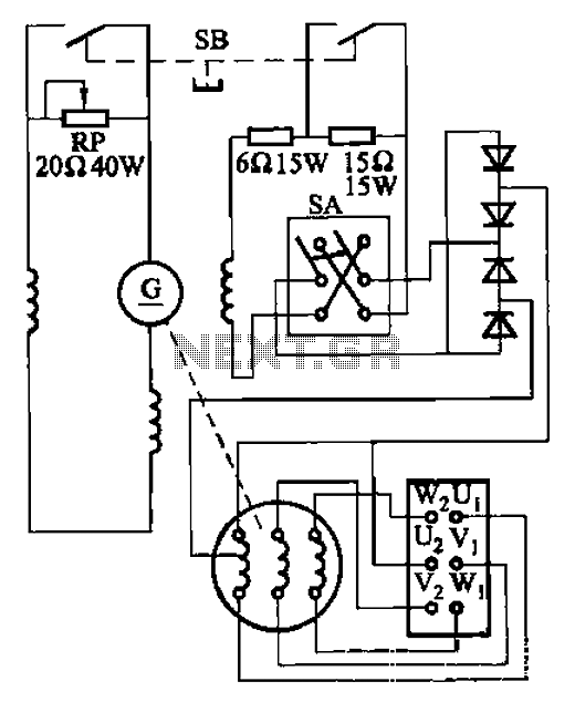
The AX3-300-2 DC arc welding machine circuit is part of the AX, AX1, AX3, and AR series of rotary DC arc welding machines. These machines share a similar structural design, featuring a three-integral unit configuration that combines an inverter...
Warning: include(partials/cookie-banner.php): Failed to open stream: Permission denied in /var/www/html/nextgr/view-circuit.php on line 713
Warning: include(): Failed opening 'partials/cookie-banner.php' for inclusion (include_path='.:/usr/share/php') in /var/www/html/nextgr/view-circuit.php on line 713