
Transmitter Servicing Course

The described circuit operates as a sophisticated transmitter system, integrating various components to ensure optimal performance under varying conditions. The main line switch (S-831) and emergency switch (S-12) are critical for initiating and maintaining operational readiness. The keying relay (K-1C) plays a vital role in grounding the center tap of the MO filament secondary of transformer T-1, which is essential for the oscillator's functionality.
The compensator transformer (T-3) is connected to the AC supply through contacts K-2B, enabling the heating of the bi-metallic compensating capacitor (C-62). This capacitor is crucial for maintaining stability in the circuit by compensating for the thermal expansion of tube elements, thereby preventing performance degradation during key-down conditions.
Temperature regulation is ensured by the thermostat (S-13), which opens its contacts when temperatures fall below 60 °C, preventing the thermostat relay (K-20) from energizing. The heating element (R-26) is activated through the normally closed contacts (K-20B) of the thermostat relay, ensuring that the compartment remains within operational limits. The thermostat's mercury column completes the circuit to the relay coil (K-20A) when the temperature exceeds the threshold, while the bi-metallic Spencer Disk (S-11) provides an additional safety mechanism, cycling the heating element between 55 °C and 71 °C.
The circuit operates as an electron-coupled Class C system, with the plate circuit precisely tuned to the second harmonic of the grid-screen grid circuit. The master oscillator range control (S-1) allows for coarse tuning in eight distinct steps, with interlock contacts (S-1C) ensuring that the keying circuit remains disengaged during adjustments. The MO calibration corrector capacitor (C-61) is an essential component for frequency adjustments, particularly when replacing tubes or components.
The circuit also features a mechanism to maintain filament voltage through switches S-3B and S-3A, which disconnect the PA filament while connecting a low power filament resistor (R-11) to ensure consistent operation. The antenna feed switch (S-6) and associated tuning components (L-13 and C-42) facilitate effective transmission by allowing for fine-tuning of the coupling between the transmitter and the antenna. The degree of coupling can be adjusted with the antenna coupling control (C-41), which directly influences the PA plate current (M-2).
Finally, keying relay contacts (K-6C) complete the DC return path for the filaments of all stages, except for the final power amplifier (PA), which utilizes a key thump filter (L-6 and R-8) for improved performance and stability. This comprehensive integration of components ensures reliable operation of the transmitter system under a variety of conditions.With the equipment ready for operation, the main line switch (S-831), the EMERGENCY SWITCH (S-12) and the main line contactor contacts K-831B all are closed. (1) The keying relay main contacts (K-1C) ground the center tap of the MO filament secondary of T-1 to complete the DC return path to the filament and allow the MO to oscillate.
(1) Conta cts K-2B connect the AC supply to the compensator transformer (T-3) to heat the compensating capacitor (C-62). This capacitor is a bi-metallic device which compensates for the changes in MD circuit capacity due to the expansion of tube elements under key-down conditions.
(b) If the temperature in the compartment is below 60 ° C, the thermostat (S-13) contacts are open, preventing the thermostat relay (K-20) from being energized. The heating element (R-26) is energized through the normally closed contacts (K-20B) of the thermostat relay.
(c) When the temperature in the compartment reaches 60 ° C, the mercury column of the thermostat (S-13) completes the circuit to the thermostat relay coil (K-20A). (e) If either S-13 or K-20 fail to operate, the temperature protection switch (bi-metallic Spencer Disk S-11) will turn the heating element (R-26) off and on within the limits of 71 ° and 55 ° C.
2. GENERAL CIRCUIT CONDITIONS: An electron coupled circuit, Class C, with plate circuit always tuned to the second harmonic of the grid - screen grid circuit. (1) Coarse tuning in 8 steps with MASTER OSCILLATOR RANGE MC control (S-1). Switch interlock contacts S-1C break the keying circuit while S-1A and B are between steps. (b) MO CALIBRATION CORRECTOR capacitor (C-61) should be set half open before the transmitter is calibrated.
When MO tubes or parts are changed, C-61 may be adjusted to make the MO frequency correspond to the previously calibrated settings. (c) Bi-metallic compensating capacitor (C-62), heated by current from T-3 whenever the key is closed, compensates for changes in MO circuit capacity due to expansion of tube elements under operating conditions.
(a) S-3B and S-3A disconnect the PA filament and connect the low power filament resistor (R-11) in series with the primary of filament transformer (T-1) to maintain 10 volts on the remaining filaments. , (a) With the ANTENNA FEED switch (S-6) in CURRENT FEED position, the antenna tuning inductance (L-13) and the antenna tuning capacitor (C-42) are connected in a series circuit.
(c) The degree of coupling between the transmitter and the antenna is adjusted with the ANTENNA COUPLING control (C-41). Increased coupling should cause an increase in PA PLATE CURRENT (M-2). (b) Keying relay contacts K-6C complete the DC return path to the filaments of all stage`s except the final PA.
The PA filament return is always complete through the key thump filter (L-6 and R-8). 🔗 External reference
Related Circuits
This operational amplifier (opamp) is available at a low cost. The AD8099 is a very fast opamp with a slew rate of 1600 V/µs and features high-impedance inputs with low input capacitance. Its bandwidth is sufficiently large that at...
This is a very simple 5 watt CW TX based upon a TTL logic chip. There is just one "tricky" component and this is Cx. This component should have an impedance of about 10 - 50 ohms at the...
A simple USB FM transmitter that can be used to play audio files from an MP3 player or computer on a standard VHF FM radio by connecting it to a USB port. The circuit does not require any coils...
Take care with transmitter circuits. It is illegal in most countries to operate radio transmitters without a license. Although only low power this circuit may be tuned to operate over the range 87-108MHz with a range of 20 or...
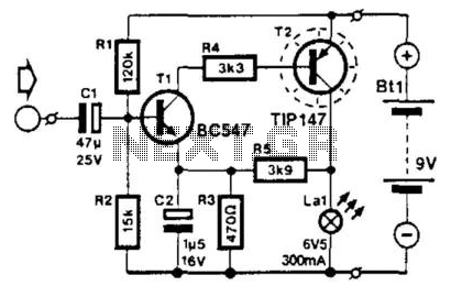
This circuit modulates the current through a lamp filament. It is designed for use with a low-voltage lamp featuring a thin, straight filament, which responds quickly to variations in filament voltage. Direct current (DC) is applied to bias the...
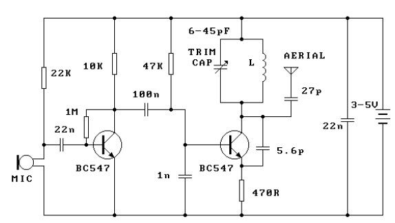
This FM transmitter circuit is very simple and has acceptable transmission. The signal transmitted from this FM transmitter circuit can be received at almost 300 meters in open air. The circuit requires a 3-volt operating voltage and can be...