
Subwoofer Low pass filter

The proposed circuit design involves an active low-pass filter that operates within the frequency range of 20 Hz to 100 Hz, effectively allowing the passage of low-frequency audio signals while attenuating higher frequencies. This filter can be implemented using operational amplifiers (op-amps), capacitors, and resistors configured in a standard second-order low-pass filter topology.
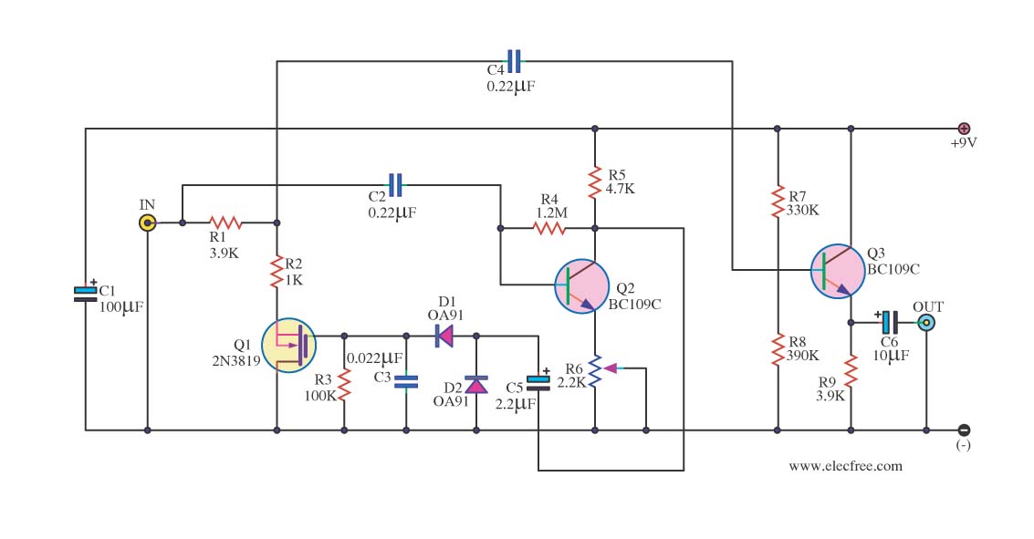
The circuit will begin with a preamplifier stage, which accepts the audio input signal from a source such as a line output from a preamplifier or directly from a music player. The output of this preamplifier will be connected to the input of the active filter circuit. The filter itself will consist of an op-amp configured in a non-inverting configuration, with feedback and input capacitors that set the cutoff frequency at 100 Hz.
To achieve the desired frequency response, the values of the resistors (R1, R2) and capacitors (C1, C2) must be carefully selected according to the formula for the cutoff frequency, which is given by:
\[ f_c = \frac{1}{2\pi R C} \]
where \( f_c \) is the cutoff frequency, \( R \) is the resistance, and \( C \) is the capacitance. For the proposed design, the components should be chosen to ensure that frequencies below 100 Hz are allowed to pass while attenuating those above this threshold.
The output of the filter will be connected to a larger subwoofer speaker, which is capable of reproducing low frequencies effectively. An additional amplifier stage may be necessary to drive the subwoofer adequately, depending on the power requirements and impedance characteristics of the loudspeaker used.
In conclusion, this circuit design will enhance the overall acoustic experience by providing a dedicated channel for low-frequency sounds, thereby improving the sound quality and depth of the audio playback system. This configuration allows for a more comprehensive auditory experience, particularly in music genres that emphasize bass frequencies.The application that to you we propose is a simple filter of region that limits the acoustic region (20-20000Hz) in the region 20-100Hz. With the manufacture that to you we propose you can make a active filter in order to you lead a loudspeaker of very low frequencies.
With this you will place one bigger speaker between the HIFI speakers of you. In order to you have a complete picture of sound you will need also the corresponding amplifier. In the entry of circuit you will connect the two exits of preamplifier or the exit of line of some preamplifier. The acoustic spectrum is extended by very low frequencies 20Iz and reaches as the 20000Iz in high frequencies. In the low frequencies is degraded the sense of direction. This reason us leads to the utilization speaker for the attribution of very low freq 🔗 External reference
Related Circuits
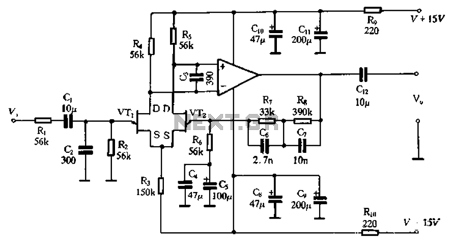
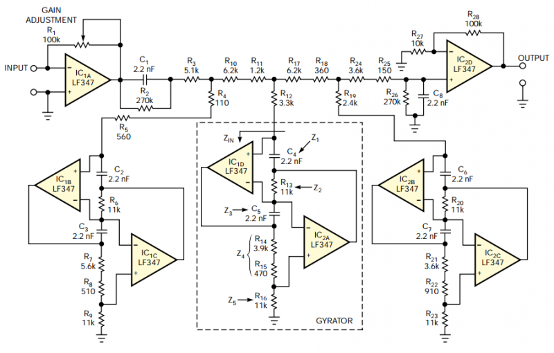
The circuit depicted in Figure 3-8 involves an input signal that passes through a low-pass filter before entering the differential amplifier. The composition of the FET (Field Effect Transistor) is evaluated at the preamplifier output. The differential amplifier connects...
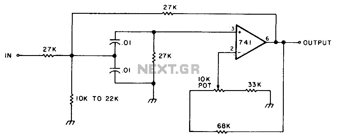
This circuit features adjustable bandwidth with a center frequency of approximately 800 Hz. A 10 kΩ potentiometer is used to adjust the bandwidth, varying from approximately ±350 Hz to ±140 Hz at the 3 dB down points. The circuit operates...
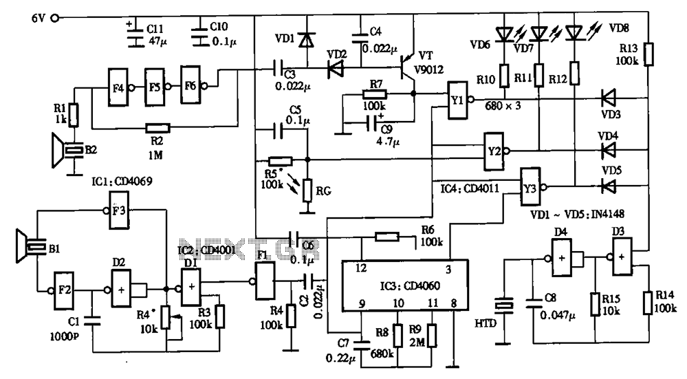
The timing circuit utilizes an electronic switch composed of F1, F2, and VT1 to reduce quiescent current to approximately 1 to 2 A with the 555 timer. Upon initial power-up, the voltage across capacitor C2 cannot instantly change, causing...
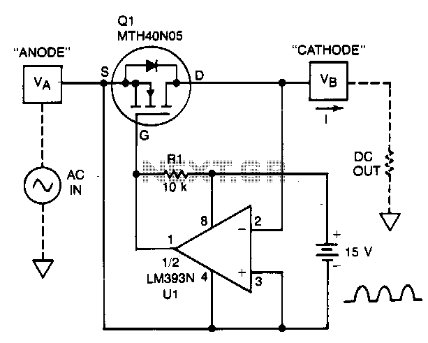
A TMOS power FET, Q1, and an LM393 comparator provide a high-efficiency rectifier circuit. When voltage V1 exceeds V2, the output of U1 becomes high, and Q1 conducts. Conversely, when V2 exceeds V1, the comparator output becomes low, and...
The filter should provide adjustable gain to maximize SNR at the audio processor's first stage. The filter's frequency response should also include a notch at 19 kHz to achieve maximum attenuation at the FM-subcarrier pilot-tone frequency and thus minimize...
In audio systems, noise signals are generally undesirable, and efforts are often made to eliminate them. Transistors can be utilized effectively for this purpose due to their availability and low noise characteristics. The following circuit serves as a Noise...