
Sun Light Chaser
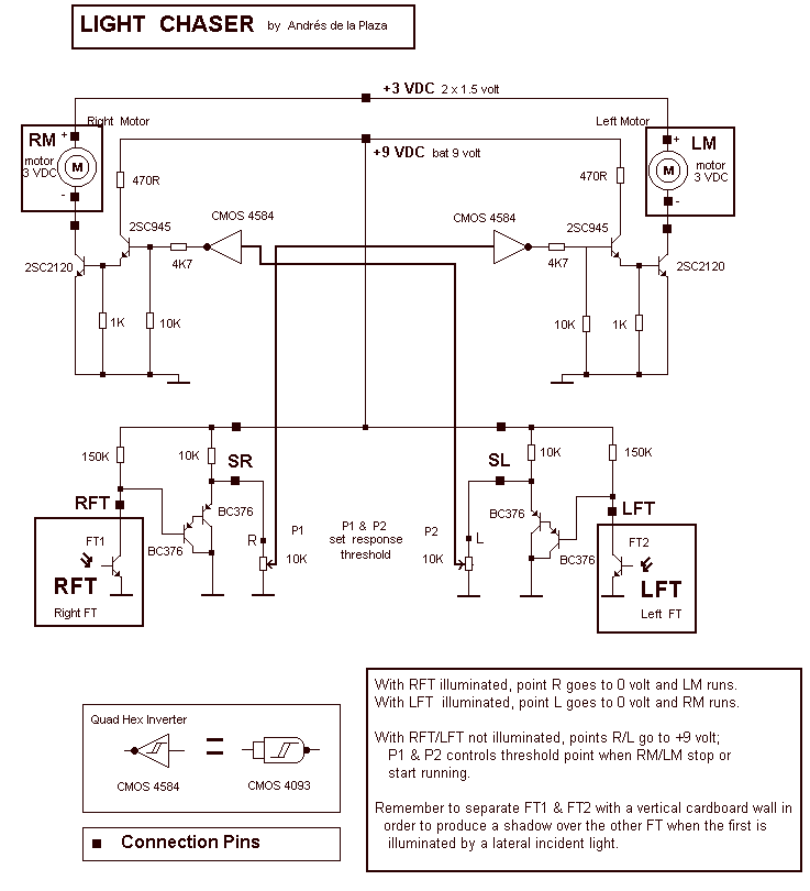
The described system appears to be a light-sensitive control circuit utilizing two photo-transistors or photo-resistors, labeled as RFT (Right Front Transistor) and LFT (Left Front Transistor). When RFT is exposed to light, it activates a corresponding control mechanism, causing point R to transition to 0 volts. This action initiates the operation of LM (Left Motor or Load). Similarly, when LFT is illuminated, point R again drops to 0 volts, activating RM (Right Motor or Load).
In the absence of illumination on both RFT and LFT, both points R and L revert to a high state of +9 volts, indicating a standby or inactive condition for the motors. The functionality of the system is further refined by the inclusion of two control points, P1 and P2, which are employed to set the threshold levels for the activation or deactivation of RM and LM. These control points likely consist of variable resistors or potentiometers that allow for fine-tuning of the sensitivity of the circuit to light levels.
To prevent interference between the two photo-sensitive components, it is crucial to implement a physical barrier, such as a vertical cardboard wall, between FT1 and FT2. This barrier is designed to create a shadow effect, ensuring that the illumination of one sensor does not inadvertently trigger the other, thus maintaining the integrity of the system's operation.
In summary, the described circuit is a light-activated control system for motors, utilizing photo-sensitive components and adjustable thresholds to manage the operation of two distinct loads based on light detection. The careful placement and isolation of the sensors are essential for optimal performance.With RFT illuminated, point R goes to 0 volt and LM runs. With LFT illuminated, point R goes to 0 volt and RM runs. With RFT and/or LFT not illuminated, points R/L go to +9 volt; P1 and P2 controls threshold point when RM/LM stop or start running. Remember to seperate FT1 and FT2 with a vertical cardboard wall in order to produce a shadow over the other FT whenthe first is illuminated by a lateral incident light.
🔗 External reference
Related Circuits
This circuit automatically controls the headlight of a motorcycle, turning it on and off independently of the light and ignition switches, as long as the battery is fully charged. The initial stage employs a 220-ohm resistor and ZD1 to...
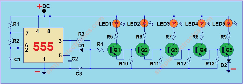
This project utilizes a 555 integrated circuit (IC) to create a sequential LED flashing effect. The configuration allows the LEDs to illuminate in a specific order, making it suitable for use as an indicator for vehicles and bicycles when...
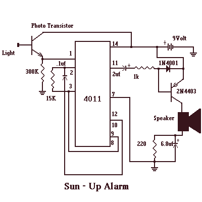
The Sun-Up Alarm can be used to provide an audible alarm for when the sun comes up or it can be used in a dark area and detect when a light comes on. It can also be used to...

One of the more advanced PCB manufacturing methods involves exposing laminate copper boards that are covered by a photoresistive layer through a mask. Utilizing UV light in the production of PCBs offers several advantages over other techniques. This method...
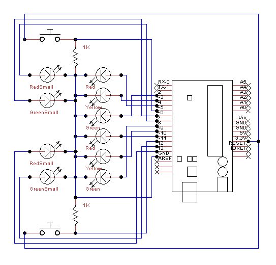
Set up the lights on the breadboard to resemble a traffic light configuration. The red LED should be positioned at the top, followed by the yellow LED, and then the green LED. The small red and green LEDs will...
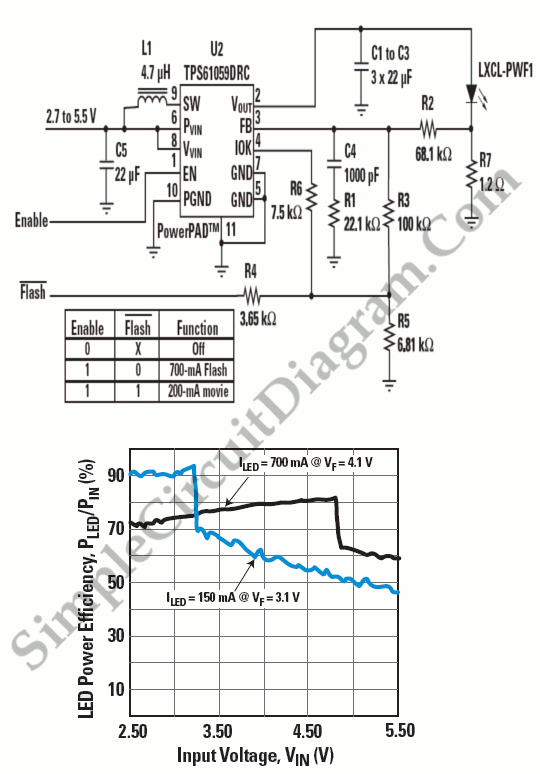
Manufacturers are beginning to utilize new high-power white-light LEDs to provide a photoflash function suitable for low-light conditions. These LEDs produce... High-power white-light LEDs have emerged as a significant advancement in lighting technology, particularly for applications requiring enhanced illumination in...