
LED Light Sequencer using 555
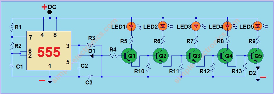
The circuit design employs a 555 timer IC configured in astable mode to generate a pulse-width modulation (PWM) signal. This signal is responsible for controlling the sequential lighting of multiple LEDs. The output from the 555 timer is connected to a series of transistors or MOSFETs that drive the LEDs, ensuring that they can handle the required current without damaging the 555 IC.
In this setup, resistors and capacitors are used to set the timing characteristics of the 555 timer, determining the frequency and duration of the LED flashes. The circuit can be designed to light up the LEDs in a left-to-right or right-to-left sequence, depending on the desired application. Additional components, such as diodes, may be included to protect against reverse polarity and to ensure that the current flows in the intended direction.
The power supply for the circuit can be derived from the vehicle's battery, typically 12V for automobiles or 6V for bicycles, with appropriate voltage regulation if necessary. The design should also consider the use of a microcontroller for more complex sequencing patterns, should the application require it.
This LED indicator project not only enhances safety by providing clear signaling during turns but also adds an aesthetic appeal to the vehicle or bicycle. Proper placement of the LEDs is crucial for visibility and effectiveness in signaling to other road users.Another 555 IC project that will flash LEDs in such a way that light turns on in a sequence. You can use this as an indicator for turning left or right for vehicles and bikes. 🔗 External reference
Related Circuits

This project was initiated in late 2003 with the aim of learning PIC programming. The goal was to create a functional device that performed a specific task. The project involves the design and implementation of a microcontroller-based system utilizing a...

The PGA202 is a digitally controlled programmable gain amplifier with gain settings of G = 1, 10, 100, and 1000. The PGA203 offers gain settings of G = 1, 2, 4, and 8. Both amplifiers are compatible with CMOS...

The circuit features red lights that chase up and down on the front of the kit, with a pause of about one second between each sequence. Unlike other circuits that continuously pulse a decade counter, this design employs two...
Is there a way to automatically turn on an LED when it gets dark? A version was created using a relay and photoresistor that functioned properly, but concerns arose regarding potential battery drain. The project aims to integrate with...
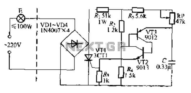
The circuit is a one-way ordinary transistor-triggered dimmer light circuit. It uses a complementary amplifier configuration with transistors VT2 and VT3 to form the thyristor trigger circuit for VT1. The circuit operates with a 220V alternating current through the...

This circuit enables the remote switching of appliances via telephone lines. It allows for the control of appliances from any distance, surpassing the limitations of infrared and radio remote controls. The design accommodates up to nine appliances, corresponding to...