
Sun wake-up call
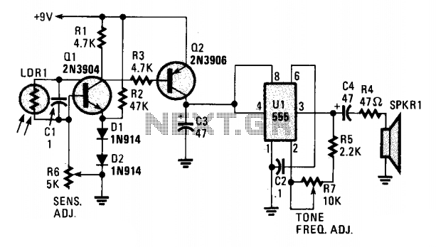
The circuit's sensitivity to light can be adjusted using R6, a 50,000-ohm potentiometer. Resistor R7 determines the audio tone, producing the most desirable sound. The square wave audio tone generated at U1 pin 3 is transmitted to a small speaker through coupling capacitor C4 and a current-limiting resistor R4.
The circuit utilizes a cadmium sulfide photocell (LDR1) that detects ambient light levels. The photocell's resistance varies inversely with the light intensity, making it an effective sensor for light-dependent applications. When exposed to light, the resistance of LDR1 decreases, allowing current to flow into the base of the NPN transistor Q1. This action activates Q1, which subsequently allows current to pass from the collector to the emitter, enabling the transistor to function as a switch.
As Q1 turns on, it generates a voltage across resistor R1, which serves to bias transistor Q2. This biasing is critical for Q2's operation, as it ensures that Q2 remains in the active state, supplying power to the 555 timer IC (U1). The 555 timer is configured in astable mode, generating a square wave output at pin 3. The frequency and duty cycle of this square wave can be influenced by the values of resistors R6 and R7, allowing the user to tailor the audio tone produced by the circuit.
The audio output from the 555 timer is coupled to a small speaker through capacitor C4, which blocks any DC component while allowing the AC audio signal to pass. Resistor R4 functions as a current-limiting component, protecting the speaker from excessive current that could potentially damage it. The overall design of this circuit provides an effective method for generating sound in response to varying light levels, making it suitable for applications such as light-activated alarms or sound-producing toys.A cadmium sulfide photocell (LDR1, which is a light-dependent resistor) is connected to the base and collector of an npn transistor, Ql. When light hits LDR1, the internal resistance goes from a very high (dark) value to a low (light) value, supplying base current to Ql, turning it on.
The voltage across Rl produces a bias that turns Q2 on, which in turn, supplies the positive voltage to Ul at pin 8 (the positive-supply input) and pin 4 (the reset input), to operate the 555 audio oscillator circuit. The circuit's sensitivity to light can be set via R6 (a 50,000 ohm potentiometer). R7 sets the audio tone to the most desirable sound. The squarewave audio tone is fed from Ul pin 3 to a small speaker through coupling capacitor C4 and current limiting resistor R4. 🔗 External reference
Related Circuits
With the world's non-renewable resources being consumed at an alarming rate, it is not surprising that the term "environmental" appeared in the key concepts of the new curriculum released 2 ½ years ago. The program of study emphasizes the...

Samsung C3330 Circuit Diagram Download Manual PDF Download. The Samsung C3330 circuit diagram serves as a comprehensive reference for understanding the electronic architecture of the device. This schematic provides detailed insights into the interconnections between various components, including the microcontroller,...
The sunset lamp activates at full brightness and gradually dims over a duration of 1.5 hours, remaining off until the power is reset. The sunset lamp circuit is designed to simulate the natural fading of sunlight, providing a calming effect...
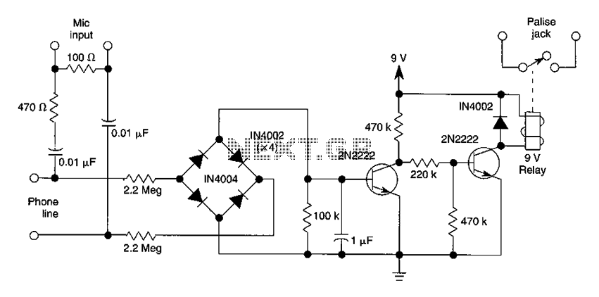
The DC voltage present on the telephone line typically ranges from 45 to 50V when on-hook and drops to approximately 6V when off-hook. This condition activates a step-down circuit relay, which in turn controls a tape recorder. Audio input...
Implementing caller ID functionality using the PIC 16F628A microcontroller. The programming and integrated circuit (IC) are functioning correctly; however, there are issues with the MT8870 decoder. Assistance is requested, particularly from those located in Malaysia, for troubleshooting ideas. The project...
This circuit gradually illuminates a 120VAC lamp over an approximate 20-minute period. A bridge rectifier provides 120V DC to the MOSFET and the 60-watt lamp. A 6.2K, 5-watt resistor and a zener diode are employed to reduce the voltage...