
1 5 hour lamp fader sunset lamp
The sunset lamp circuit is designed to simulate the natural fading of sunlight, providing a calming effect as it transitions from full brightness to complete darkness. The primary components of this circuit include a microcontroller, a power supply, an LED light source, and a dimming control mechanism.
The microcontroller serves as the central processing unit, programmed to manage the timing and brightness levels of the LED. It receives power from an AC to DC converter, which supplies the necessary voltage to the circuit. The LED light source is typically a high-power RGB LED or a warm white LED, chosen for its ability to produce a soft, ambient glow.
To achieve the gradual dimming effect, the microcontroller utilizes a pulse-width modulation (PWM) technique. This method involves rapidly turning the LED on and off at varying duty cycles, which effectively controls the perceived brightness. The transition from full brightness to darkness is programmed to occur over a set period of 1.5 hours.
The circuit also includes a power reset feature, which allows the lamp to remain off until the power supply is recycled. This is accomplished through a relay or a solid-state switch that disconnects the power from the LED after the fading sequence is complete. When the power is restored, the microcontroller resets, initiating the full brightness phase once again.
In summary, the sunset lamp circuit combines a microcontroller, LED light source, and PWM dimming control to create a soothing light transition, enhancing the ambiance of any space while incorporating an energy-efficient design.The sunset lamp comes on at full brightness and then slowly fades out over 1.5 hours time and stays off until power is recycled.. 🔗 External reference
Related Circuits

This NiCAD battery charger circuit charges the battery at 75 mA until it is fully charged, after which it reduces the current to a trickle rate. It can completely recharge a dead or unpowered battery in 4 hours, and...

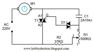
A very simple dimmer circuit with only the essentials. In this circuit, the values are given for a BT138 at 220V AC. For 115V AC, experimentation with values may be necessary. R1 can vary from one triac to another;...
The headlamp schematic for the Daewoo Korando is illustrated in the accompanying figure. It details the connections and wiring between various components of the vehicle's headlamp system, including the alternator, ignition switch, buy-off switch, high lamp relay, low lamp...
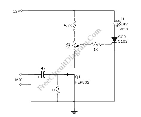
This simple circuit illustrated in the schematic diagram activates the switch using sound. It can be utilized for various applications, such as automatic (sound-controlled) disco lights or car LED light shows. The transistor Q1 amplifies the audio from the...
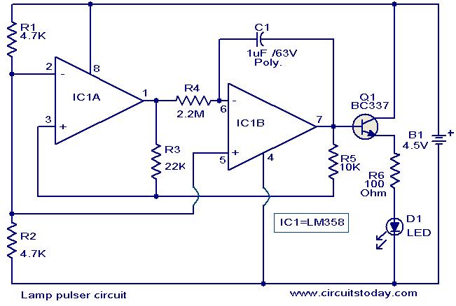
This circuit is designed to gradually pulse an LED or a low-power filament lamp, creating a visual effect where the light transitions from an OFF state to full brightness and then back down to OFF. Such a circuit is...

Here is a design for a temporary lamp circuit that is very helpful in emergency situations or in any application where there is limited time to turn off the lamp. Simply press the push button to perform a quick...
Warning: include(partials/cookie-banner.php): Failed to open stream: Permission denied in /var/www/html/nextgr/view-circuit.php on line 713
Warning: include(): Failed opening 'partials/cookie-banner.php' for inclusion (include_path='.:/usr/share/php') in /var/www/html/nextgr/view-circuit.php on line 713