
Super AC dimmer using IC-555& triac

The super dimmer operates using advanced technology that allows for finer control over light intensity, enhancing the user experience. It typically employs a phase-cut dimming technique, which can be either leading-edge or trailing-edge, depending on the application and the type of load connected.
In a typical schematic for a super dimmer, key components include a microcontroller, a TRIAC (Triode for Alternating Current), and associated passive components such as resistors, capacitors, and inductors. The microcontroller serves as the brain of the dimmer, processing user inputs and controlling the TRIAC's gate to adjust the power delivered to the load.
The circuit begins with an AC supply, which is connected to the input of the super dimmer. The microcontroller receives user input through a potentiometer or a digital control interface, allowing the user to set the desired brightness level. The microcontroller processes this input and determines the appropriate phase angle for the TRIAC.
When the TRIAC is triggered at the right moment during the AC cycle, it allows current to flow to the load (such as an incandescent bulb or LED). By adjusting the point at which the TRIAC is triggered, the average power delivered to the load can be controlled, effectively dimming the light output.
Additional components may include snubber circuits to protect the TRIAC from voltage spikes and filters to reduce electromagnetic interference. The super dimmer may also incorporate features such as over-temperature protection, soft-start capabilities, and compatibility with various lighting technologies, including LED, CFL, and incandescent lamps.
The design and implementation of the super dimmer can significantly enhance energy efficiency and extend the lifespan of connected lighting fixtures, making it a valuable addition to modern lighting systems.The super dimmer it is certainly better than the normal dimmer you are using now. It would be better, however, to try to prove it. Let`s see how it works.. 🔗 External reference
Related Circuits
Humanity has long grappled with the concept of Time, often seeking ways to interact with it meaningfully. A proposed solution is a knocking platform designed to address these fundamental needs, exemplified by the Knock Block KUI and its associated...
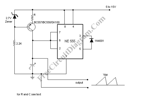
A sawtooth wave oscillator circuit can be implemented using several methods. Here, one design that employs the 555 integrated circuit is presented, along with its schematic diagram. The sawtooth wave oscillator utilizing the 555 timer IC operates in astable mode,...

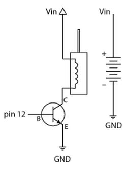
The IR photo transistor Q1 (Radio Shack 276-145A) or a similar component is connected to the set input (pin 6). It is essential to shield the photo transistor from direct light to ensure that the voltage at the set...
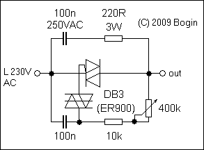
This circuit, commonly referred to as the poor man's variac, is utilized in various applications across consumer and industrial electronics where a perfectly sinusoidal waveform is not necessary, and a traditional variac (variable autotransformer) would be excessively heavy and...
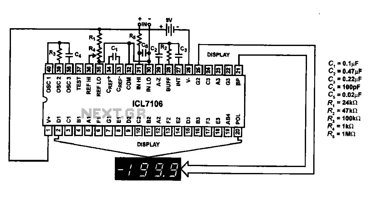
This circuit utilizes the ICL7106 / ICL7107 chip to drive a liquid crystal display (LCD). In this configuration, the ICL7106 / ICL7107 functions as a signal measurement and analog-to-digital (A/D) converter. It detects an analog input signal, amplifies it,...

This is an affordable method for measuring temperature and humidity with a computer interface, designed as an entry-level project for high school students on a limited budget. The project involves the integration of a temperature and humidity sensor, such as...