
Super boost bass by UA741
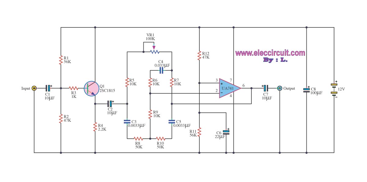
The super boost bass circuit utilizes a low-pass filter configuration to effectively attenuate higher frequency signals while allowing lower frequencies to pass through. This is particularly beneficial for audio applications where bass enhancement is desired, such as in home theater systems, car audio setups, or personal audio devices.
The circuit typically consists of passive components such as resistors, capacitors, and sometimes inductors, arranged to define the cutoff frequency. The cutoff frequency is a critical parameter that determines the point at which the filter begins to attenuate higher frequencies. The design can be adjusted to achieve the desired bass response by selecting appropriate component values based on the desired audio characteristics.
In practical applications, the circuit can be integrated with audio amplifiers or used in standalone configurations. The output of the low-pass filter is connected to the audio output stage, ensuring that the enhanced bass frequencies are delivered to the speakers or headphones.
Additionally, the circuit may include features such as gain control to adjust the level of bass enhancement, and it can be designed to operate with various audio sources, providing versatility in its use. Overall, this super boost bass circuit is an effective solution for audio enthusiasts seeking to enrich their listening experience with deeper bass tones.Super boost bass circuit this be low pass filter circuit model,which will low pass filter. By give bass audio that firm then convenient for a person who like.. 🔗 External reference
Related Circuits
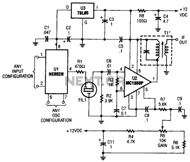
By using an NE602 with a filter and an MC1350P IC, a front end and an IF system for a basic superheterodyne receiver can be built with few parts. Tl is any suitable IF transformer for 262 kHz, 455...
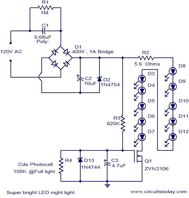
The circuit diagram illustrates a super bright LED night lamp that operates from the mains supply. A bridge rectifier (D1) is employed to convert the AC mains voltage into DC. The combination of capacitor (C1) and resistor (R1) forms...
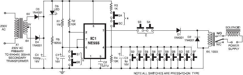
A simple electronic key code lock circuit that requires few external components can be constructed using this schematic diagram. This electronic key code lock circuit is based on a common 555 timer circuit and other standard components. This low-cost...
This preamplifier was designed to cope with CD players, tuners, tape recorders etc., providing a gain of 4, in order to drive less sensitive power amplifiers. As modern Hi-Fi home equipment is frequently fitted with small loudspeaker cabinets, the...
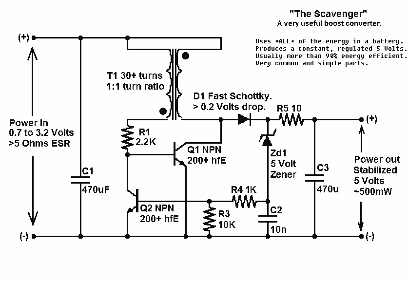
Presented here is a significant advancement in the design of simple, cost-effective, and efficient boost converters. To achieve an effective design, it is essential to convert current to voltage as efficiently as possible. This circuit excels in this regard. The...
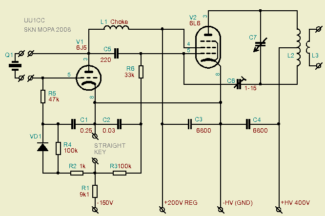
A Pierce "aperiodic" oscillator drives a non-neutralized power amplifier for a multiband Morse code transmitter that requires only one coil and minimal adjustment. This document examines the topology of the Boosted Pierce oscillator, tracing its evolution from its origins...